Page 19
LFS Height Adjustable Arm Tension
Adjustment
a. Check the vertical tension adjustment of the
Height Adjustable Arm for its capacity to support
the flatscreen monitor throughout its range of mo-
tion. The monitor should move freely yet maintain
its selected position without drifting. If an adjust-
ment is necessary, refer to figure 19 and proceed
as follows:
NOTE
The System can support and balance a
monitor weight up to 20 lbs. Exceeding
the weight will result in poor balance
and performance.
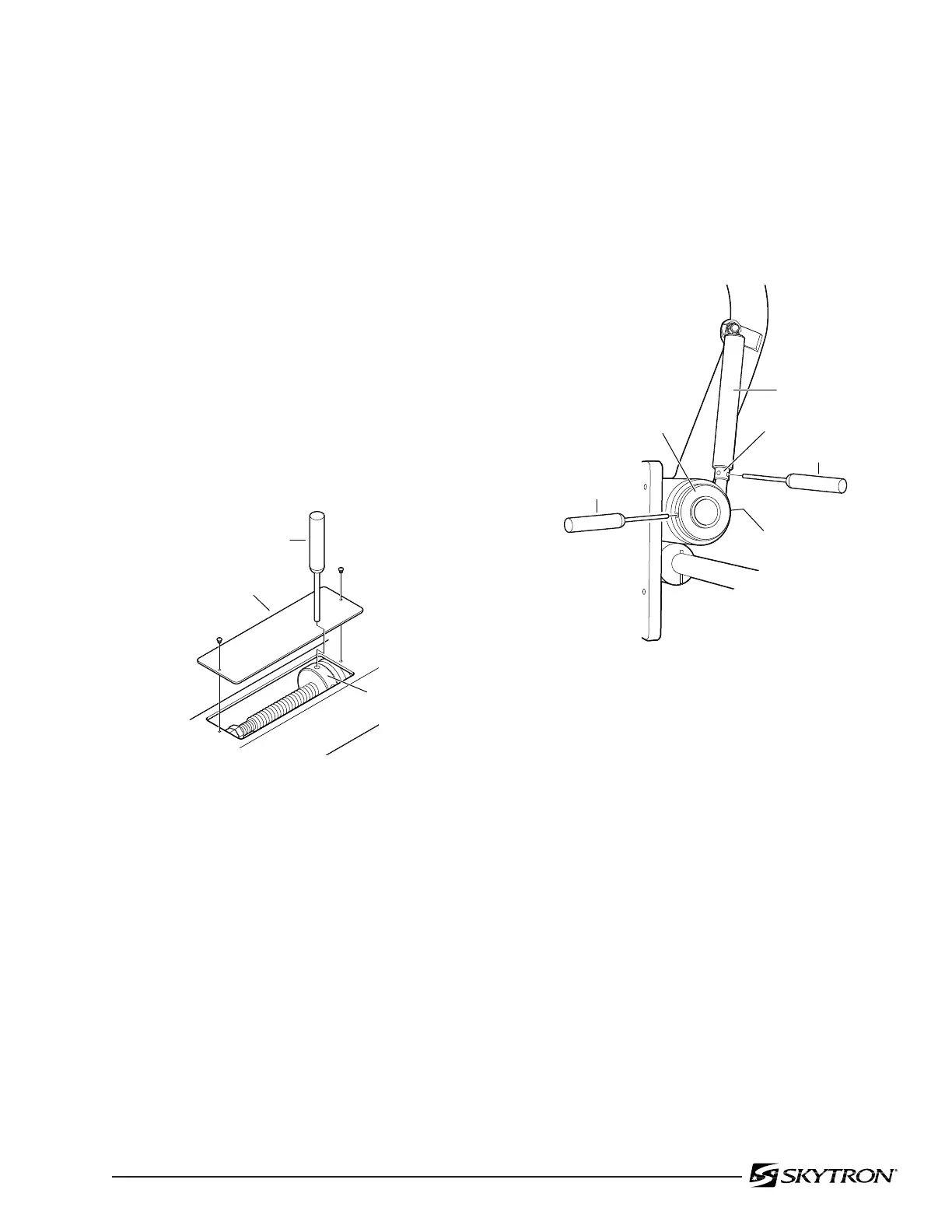
Figure 19
b. Remove the cover plate on the top of the
Height Adjustable Arm for access to the tension
adjustment nut. Insert a 1/8" pin punch into a hole in
the adjustment and turn the nut as required to
achieve proper tension - clockwise to increase
tension, counterclockwise to decrease tension.
Replace access cover when adjustment is com-
plete.
Figure 20
d. Loosen set screw on trunnion nut, insert a
1/8" pin punch into hole opposite set screw location
and adjust trunnion nut as required - clockwise to
increase tension, counter clockwise to decrease
tension. Tighten set screw when adjustment is
complete.
e. For fine adjustment, rotate the monitor down-
ward until the adjustment nut is visible on the
tension spring assembly. Using a pin punch, turn
the adjustment nut until proper tension is achieved.
c. Check the adjustment for the flatscreen
monitor pitch axis. The monitor should move freely
yet maintain its selected position without drifting. If
an adjustment is necessary, refer to figure 20 and
proceed as follows:
COVER PLATE
1/8" PIN PUNCH
ADJUSTMENT
NUT
PIN PUNCH
1/8"PIN
PUNCH
ADJUSTMENT NUT
TRUNION
NUT
SET SCREW
TENSION SPRING

 Loading...


