Page 7
TYPICAL INSTALLATION SEQUENCE /
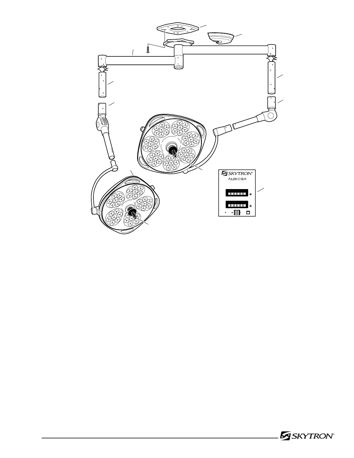
COMPONENT IDENTIFICATION
1. Mounting Plate
2. Radial Arm Assembly(RAA)
3. Ceiling Cover
4. Vertical Support Tube(VST)
INSTALLATION NOTES
•TheSKYTRONSurgicalLightingFixtureisnor-
mally shipped in two to four crates, depending on
the model. A carton containing the Vertical Sup-
port Tubes, miscellaneous hardware, and various
instructional materials is packed separately.
•FollowtheInstallationInstructionsandutilizethe
Installation Check List to assure proper installa-
tion.
•Specialadapter platesfor mountingSKYTRON
surgical lights on existing mounting structures are
available. Contact your SKYTRON representative
for special application details.
•Additionalmaterialsrequiredforproperinstallation
include Loc-Tite compound.
•Aurora Series lighting xtures require a wall
mounted control box. Single and Dual Lighthead
models 8" x 10", for Triple 10" x 13-1/2". 3/4" metal
conduit and minimum 12 AWG wire is required
between wall control and fixture.
•Contact SKYTRON representative for Seismic
calculations if applicable.
5. Balance Mechanism(BOM)
6. Lighthead
7. Sterilizable Positioning Handle
8. Wall Control
1
3
4
4
5
5
2
8
7
7
6
20,000 HOUR
INDICATOR
COLOR TEMPERATURE
INDICATOR
4,500K WHEN ILLUMINATED
MAIN POWER
2A, 250V
Fast Acting
2A, 250V
Fast Acting
0 1 2 3 4 5
0 1 2 3 4 5

 Loading...


