Page 13
WARMING CABINET OWNER’S
• REV2
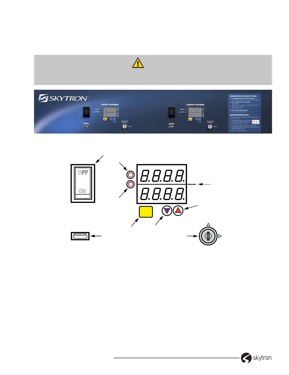
4-1. Standard Controls
The controls are located on the upper panel on the front of the cabinet. For dual-chamber cabinets there
are individual controls for each chamber. Each control is clearly labeled UPPER and LOWER for the dual
chamber cabinet (Figure 8).
WARNING
The USB port should only be used for downloading temperature history data. DO NOT connect
USB wireless devices due to potential EMI conditions.
Figure 8. Standard Data Control Panel
OFF
ON
HEAT
ALARM
UPPER CHAMBER
DATA
ALARM
RESET
ACTUAL SETPOINT
SETPOINT
UNLOCK
LOCK
1
8
7
6
3
2
9
5
4
SET
Figure 9. Control Components
1. ON/OFF Switch/Circuit Breaker – provides
power to the warming compartment and
control.
2. HEAT light – visual indicator that the heating
system is active
3. ALARM light – visual indicator of an overheat
condition.
4. Display – shows the current chamber
temperature (Actual) and the setpoint
temperature in Fahrenheit (F) or Celsius (C).
The display also provides Loss of Power and
the Overheat (alarm). The overheat alarm is an
audible and visual display ‘HI’.
5. Up ▲– used to adjust the setpoint of the chamber
and silence the audible overheat alarm.
6. Down ▼– used to adjust the setpoint of the
chamber.
7. SET Button – press to use the Up/Down arrows
to change the setpoint temperature and press
again to lock the new value.
8. DATA port – USB port used to retrieve
temperature values for a set period of
time.
9. Key switch – used to lock out any changes to
the control.
SECTION 4. CONTROLS