Page 18
WARMING CABINET OWNER’S
• REV2
4-2-7. Data File
−Data File Naming
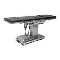
1. Touch: (1) Home (2)Monitor (3) swipe screen
left-to-right, touch (4)Data (Figure 24).
Data
S
W
I
P
E
3
MM/DD/YYYY
HH:MM AMPM
2
1
4
Figure 24. Data Icon Screen
2. Data screen, Touch: (1)Square in Data box, turns
dark green to allow input (2)File Name box opens
keypad –
see Figure 15
. Key le name - max 16
characters, touch Done
−Data Logging
1. Touch: (3)Length(days) box opens keypad–see
Figure 26. Key 1-to-31 days to be logged–once
elapsed a new file is started (Figure 25).
NOTICE
File saves as:
Filename_mm_dd_yyyy_hh_mm_ss.
Data
Data
Length(days) 1
File Name S2-0001-TSkytron
ID#1 7891011
Start Program Fixed Interval
Interval (sec) 60
ID#2
OFF
OFF
ON
2
3
4
6
8
7
5
MM/DD/YYYY
HH:MM AMPM
1
Figure 25. Data Screen
2. Touch: (4)Interval (sec) opens keypad (Figure
26). Key 2-to-1860 seconds, duration data will be
logged (5)Fixed Interval must be OFF.
Length (days) or Interval (secs)
<-- Clear
Cancel Done
1 2 3
4 5 6
7 8 9
+ - 0
Min:
Max:
Figure 26. Interval (secs) Keypad
3. Touch: (6)ID#1 or #2 for added le identication.
If: (5)Fixed Interval is ON, interval is based on
Length(days) with 1 day equal to a 1 minute
interval, 7 days, the logging rate is every 7 minutes.
(7)Program OFF. Touch (8)ON automatically
turns on data logging (see Figure 25).
−Data Logging Variables
Variables must be assigned to the data le. Choose
which data points are to be logged by touching the
Assign icon.
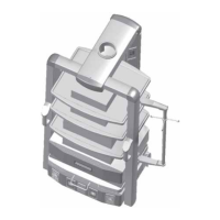
1. Touch: (1)Home (2)Monitor (3)Swipe
left-to-right, touch (4)Assign icon to open
Assign screen (Figure 27).
Assign
S
W
I
P
E
3
MM/DD/YYYY
HH:MM AMPM
2
1
4
Figure 27. Assign Icon
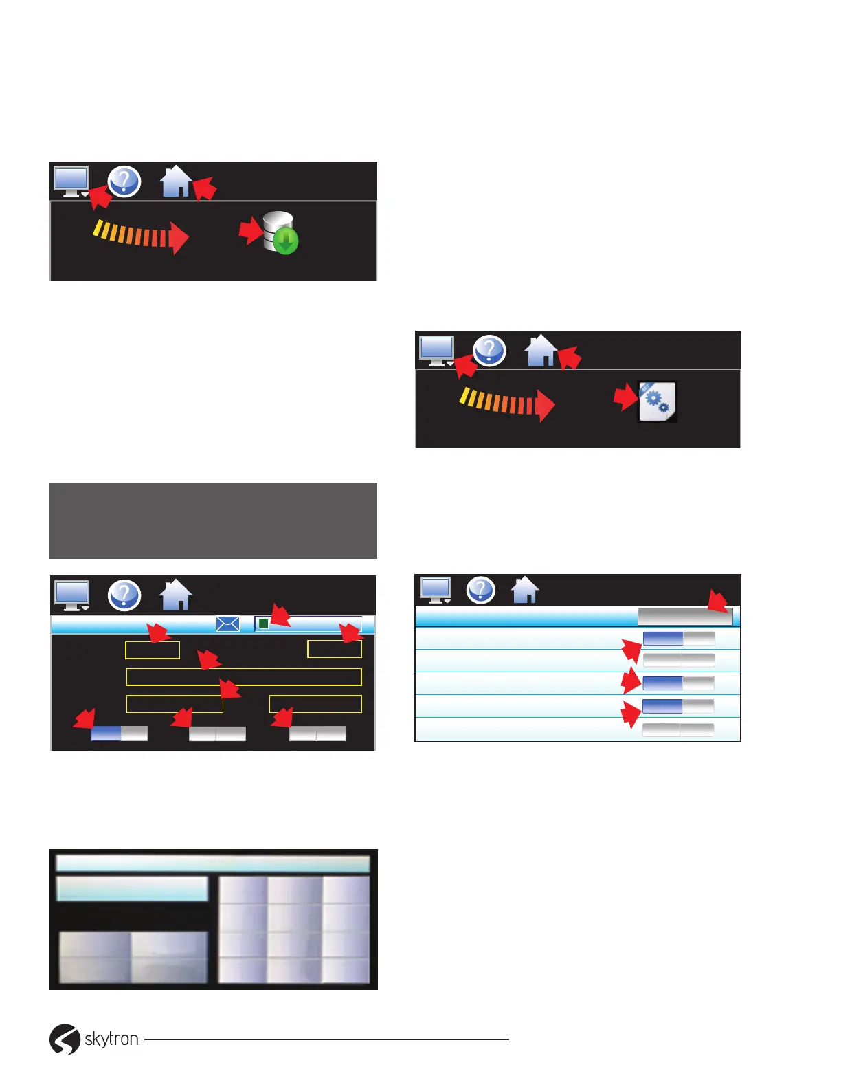
2. At Assign screen, Slide ON: (1)Upper Temp
PV (2)Upper Temp %Out (3) Lower Temp PV.
Touch (4) Save, Data le settings have been
saved pop-up, touch OK (Figure 28).
Assign
Upper Temp PV
Upper Temp SP
Upper Temp %Out
Lower Temp PV
Lower Temp SP
ON
ON
ON
Save
MM/DD/YYYY
HH:MM
AMPM
1
3
OFF
OFF
2
4
Figure 28. Assign Screen - Dual Chamber
4-2-8. Chart Setup
−Real-time charts
Display PV, SP and %Out. Vertical axis determine
range horizontal axis determine time period
maximum of 24 hours.
1. Touch: (1)Home (2)Monitor (3)Swipe
left-to-right, touch (4)Chart (Figure 29).