94 MN.00273.E - 004
8.10 GROUNDING
The ODU must be connected to ground with the available grounding bolt and eyelet terminal, making ref-
erence to details of Fig.34
.
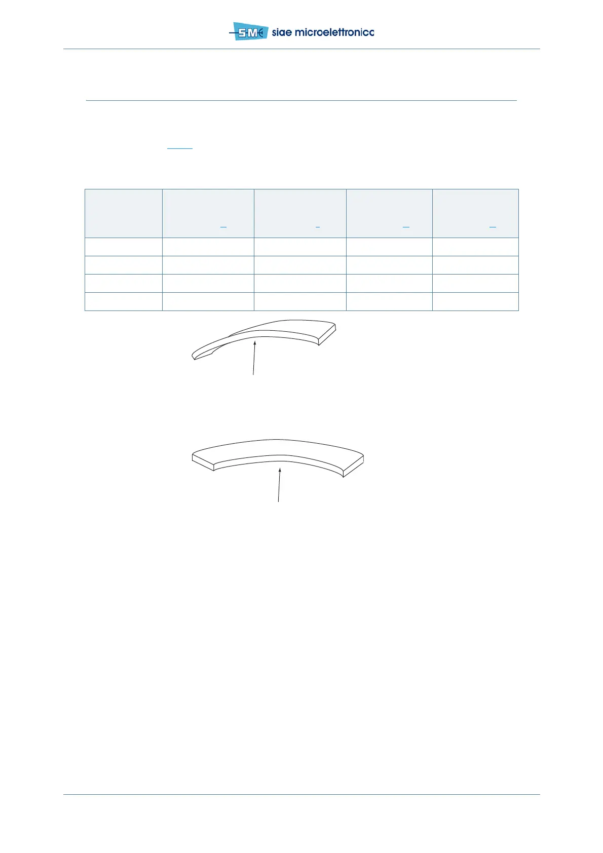
Tab.22 - Waveguide bending radius according to frequency
Frequency
Bending radius with-
out rebending
mm (inch)
E-plane
a
a. Bending E-plane
Bending radius with-
out rebending
mm (inch)
H-plane
b
b. Bending H-plane
Bending radius with
rebending
mm (inch)
E-plane
a.
Bending radius with
rebending
mm (inch)
H-plane
b.
15 GHz 130 (5,1) 280 (11,0) 150 (5,9) 300 (11,9)
18 GHz 130 (5,1) 280 (11,0) 150 (5,9) 300 (11,9)
23 GHz 110 (4,3) 230 (9,1) 130 (5,1) 250 (9,9)
38 GHz 80 (3,1) 140 (5,5) 90 (3,6) 150 (5,9)
Rmin/E
Bending E-plane
(short side of the section)
Rmin/H
Bending H-plane
(long side of the section)
 Loading...