SMA Solar Technology AG Safety
Installation Guide SB13_21TL-IA-IEN121060 11
2.3 Explanation of Symbols
This section gives an explanation of all the symbols found on the inverter and on the type label.
2.3.1 Symbols on the Inverter
* This function is valid from firmware version 4.00
** optional
*** QR-Code is a registered trademark of DENSO WAVE INCORPORATED.
Grounding the PV array
Comply with the local regulations for grounding the modules and the PV array. SMA Solar
Technology AG recommends connecting the array frame and other electrically conductive
surfaces so that there is continuous conduction and to ground them in order to ensure
maximum protection for plants and persons.
Symbol Explanation
Operation display.
Indicates the operating state of the inverter.
Ground fault or varistor defective.
Read section 9.3"Red LED is Glowing Continuously" (page52).
Error or fault.
Read section 9"Failure Search" (page46).
You can operate the display by tapping on the enclosure lid:
• Tapping once: the backlight switches on or the display scrolls to the
next display message.
• Tapping twice in quick succession*: the inverter shows the display
messages from the startup phase again (see Section 6.2"Display
Messages during the Startup Phase" (page38)).
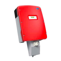
Electronic Solar Switch (ESS) DC switch-disconnector**.
• When the Electronic Solar Switch is plugged in, the DC circuit is
closed.
• To interrupt the DC circuit and disconnect the inverter securely
under load, you have to first pull out the Electronic Solar Switch
and then remove all DC connectors , as described in section
7.2"Opening the Inverter" (page39).
QR-Code®*** for SMA bonus program
You will find information on the SMA bonus programme at
www.SMA‑Bonus.com.
 Loading...
