Installation
1.5
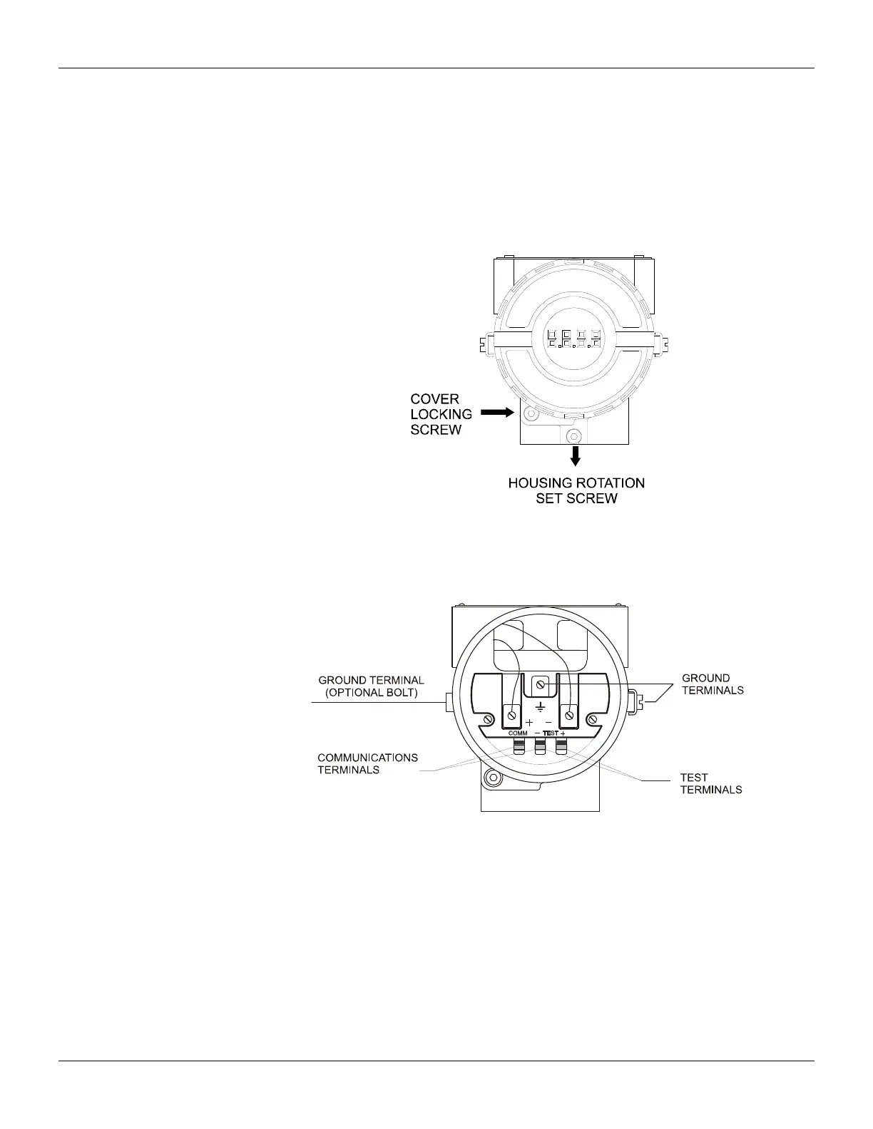
Housing Rotation
The electronic housing can be rotated in order to better position the digital display. To rotate it, uses
the housing rotation set screw, see figure 1.4.
The local indicator itself can also be rotated. See section 5, figure 5.2.
Electric Wiring
Reach the wiring block by removing the electrical connection cover (figure 1.4). This cover can be
locked closed by the cover locking screw. To release the cover, rotate the locking screw clockwise.
Figure 1.4 – Cover Locking and Housing Rotation Set Screw
The wiring block has screws on which fork or ring-type terminals can be fastened. See figure 1.5.
For convenience there are two ground terminals: one inside the cover and one external, located
close to the conduit entries.
Figure 1.5 – Wiring Block
The TP303 uses the 31.25 kbit/s voltage mode option for the physical signaling. All other devices on
the same bus must use the same signaling. All devices are connected in parallel along the same
pair of wires.
Various types of Fieldbus devices may be connected on the same bus.
The TP303 is powered via the bus. The limit for such devices is according to DP/PA coupler
limitations for one bus for non-intrinsically safe requirement.
In hazardous area, the number of devices may be limited by intrinsically safe restrictions, according
to the DP/PA couples and barriers limitations.
The TP303 is protected against reverse polarity, and can withstand ±35 VDC without damage, but it
will not operate when in reverse polarity.