TP303 - Operation, Maintenance and Instructions Manual
4.2
NOTE
The Factory Init should be tried as a last option to recover the equipment control when the equipment
presents some problem related to the function blocks or the communication. This operation must only be
carried out by authorized technical personnel and with the process offline, since the equipment will
be configured with standard and factory data.
This procedure resets all the configurations run on the equipment, after which a partial download should be
performed.
Two magnetic tools should be used to this effect. On the equipment, withdraw the nut that fixes the
identification tag on the top of the housing, so that access is gained to the "S" and "Z" holes.
The operations to follow are:
1) Switch off the equipment, insert the magnetic tools and keep them in the holes (the magnetic end in the
holes);
2) Feed the equipment;
3) As soon as Factory Init is shown on the display, take off the tools and wait for the "S" symbol on the
right upper corner of the display to unlit, thus indicating the end of the operation.
This procedure makes effective all factory configuration and will eliminate eventual problems with the
function blocks or with the equipment communication.
Disassembly Procedure
Refer to TP303 Exploded View figure (Figure 4.3). Make sure to disconnect power supply before
disassembling the position transmitter.
NOTE
The numbers indicated between parentheses refer to Figure 4.3 – Exploded View.
Transducer
To remove the transducer from the electronic housing, the electrical connections (in the field
terminal side) and the main board connector must be disconnected
Loosen the hex screw (6) and carefully unscrew the electronic housing from the transducer,
observing that the flat cable is not excessively twisted.
Electronic Circuit
To remove the circuit board (5) and indicator (4), first loose the cover locking (6) on the side not
marked Field Terminals, then unscrew the cover (1).
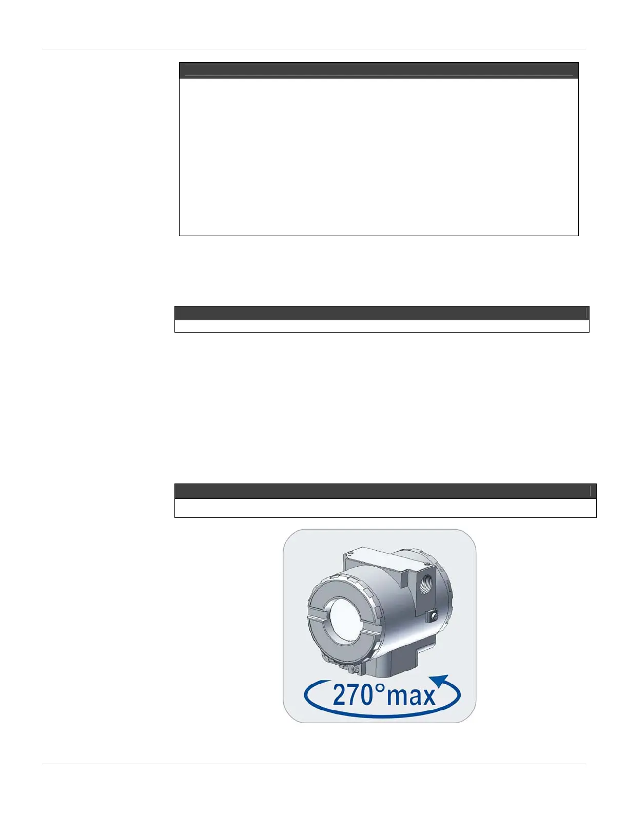
CAUTION
Do not rotate the electronic housing more than 270° without disconnecting the electronic circuit from the power
supply.
Figure 4.1 - Sensor Rotation