TP303 – Operation, Maintenance and Instructions Manual
3.12
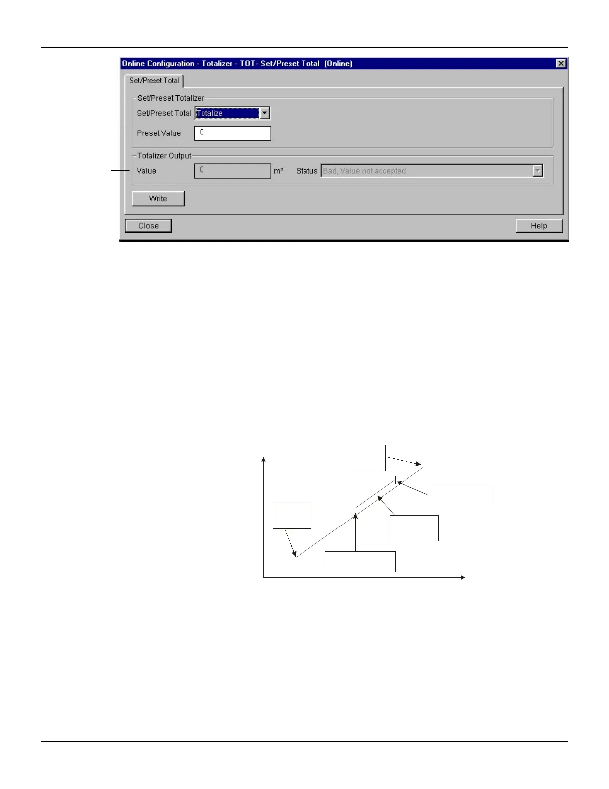
Figure 3.10 - Simatic PDM - Online Configuration - Set/Preset for Totalizer Block
Lower and Upper Trim
This information is provided to recommend parameters for a common user calibration method for
position device.
The calibration process is used to match the channel value reading with the applied position input.
Six parameters are defined to configure this process: CAL_POINT_HI, CAL_POINT_LO,
CAL_MIN_SPAN, SENSOR_UNIT, SENSOR_HI_LIM and SENSOR_LO_LIM. The CAL_*
parameters define the highest and lowest calibrated values for this sensor, and the minimum
allowable span value for calibration. SENSOR_UNIT allows the user to select different units for
calibration purposes than the units defined by PRIMARY_VALUE_UNIT.
The SENSOR_HI_LIM and SENSOR_LO_LIM parameter defines the maximum and minimum
values the sensor is capable of indicating, according to SENSOR_UNIT used as it can be seen at
figure below.
Sensor
Lo Lim
Sensor
Hi Lim
CAL_POINT_LO
0.0 %
CAL_POINT_HI
100.0 %
TRIMMED VALUE
SENSOR VALUE
Calibrated
Range
Figure 3.11 - Hall Sensor Calibration
The trim is used to match the reading value with the applied position.
Lower Trim: It is used to trim the reading at the lower range. The operator informs to the TP303 the
correct reading for the position.
Upper Trim: It is used to trim the reading at the upper range. The operator informs to the TP303 the
correct reading for the position.
Using a configurator is possible to calibrate the converter by means of parameters CAL_POINT_LO
and CAL_POINT_HI. This engineering unit is configured by SENSOR_UNIT parameter. The unit
code is %. The calibrated value can be read by means TRIMMED_VALUE.
totalize, reset and
enter the value for
The user can monitor