Maintenance Procedures
4.3
WARNING
The board has CMOS components, which may be damaged by electrostatic discharges. Observe correct
procedures for handling CMOS components. It is also recommended to store the circuit boards in electrostatic-
proof cases.
Pull the main board out of the housing and disconnect the power supply and the sensor connectors.
Reassembly Procedure
WARNING
Do not assemble the main board with power on.
Electronic Circuit
Plug sensor connector and power supply connector to main board.
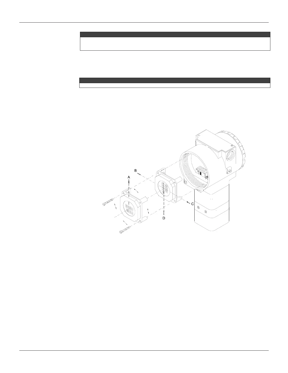
Attach the display to the main board. Observe the four possible mounting positions. The Smar mark
indicates up position.
Figure 4.2 - Four Possible Positions of the Display
Upgrading TP301 to TP303
The sensor and casing of the TP301 is the same as the TP303. By changing the circuit board of the
TP301 it becomes a TP303. The display on TP301 version 1.XX, is the same as on TP303 and can
therefore be used with the TP303 upgrade circuit board.
Upgrading the TP301 to a TP303 is therefore very much the same as the procedure for replacing
the main board described above.
To remove the circuit board (5), loosen the two screws (3) that anchor the board.
Caution with the circuit boards must be taken as mentioned above.
Pull the TP301 main board out of the housing and disconnect the power supply and the sensor
connectors.
Put in the TP303 main board reversing the procedure for removing the TP301 circuit.