Installation
1.7
Analog
Ground
+
-
+
-
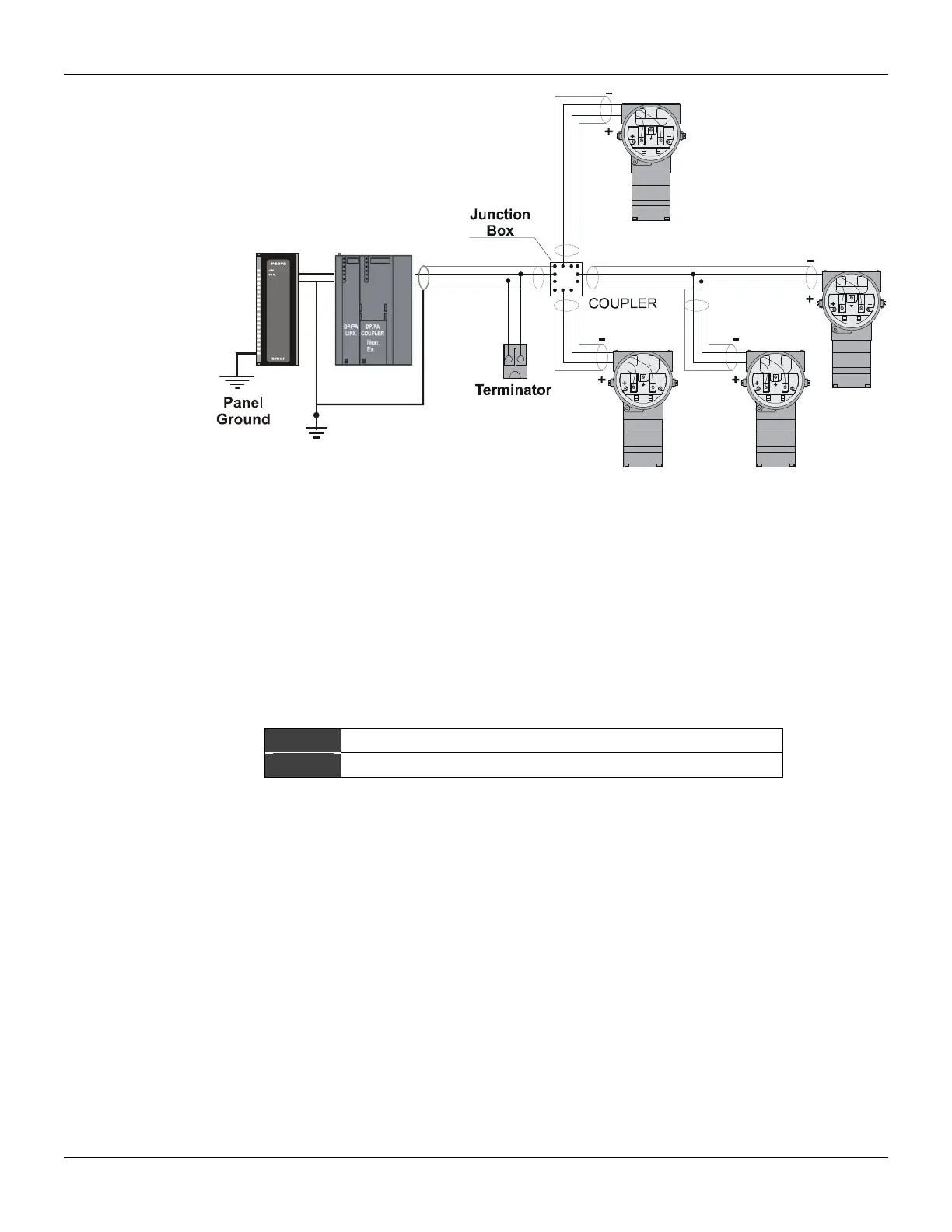
Figure 1.7 - Tree Topology
Intrinsic Safety Barrier
When the Fieldbus is in an area requiring intrinsic safety, a barrier must be inserted on the trunk
between the power supply and the DP/PA coupler, when it is Non-Ex type.
Use of DF47 is recommended.
Jumper Configuration
In order to work properly, the jumpers J1 and W1 located in the TP303 main board must be correctly
configured.
J1 This jumper enables the simulation mode parameter in the AI block.
W1 This jumper enables the local adjustment-programming tree.
Table 1.1 - Description of the Jumpers
Power Supply
The TP303 receives power from the bus via the signal wiring. The power supply may come from a
separate unit or from another device such as a controller or DCS.
The voltage should be between 9 to 32 Vdc for non-intrinsic safe applications.
A special requirement applies to the power supply used in an intrinsically safe bus and depends on
the type of barrier used.
Use of PS302 is recommended as power supply.
Remote Hall Sensor
The remote Hall magnetic sensor is recommended for applications where there are high
temperatures and extreme vibrations applications. It prevents excessive wear of the equipment and,
consequently, the reduction of its useful lifetime.