Section 2
2.1
OPERATION
Functional Description – Hall Sensor
Sensor Hall supplies an output voltage proportional to the applied magnetic field. This magnetic
sensor is ideal for use in system of sensor of linear or rotative position. The mechanical vibrations
do not affect Sensor Hall.
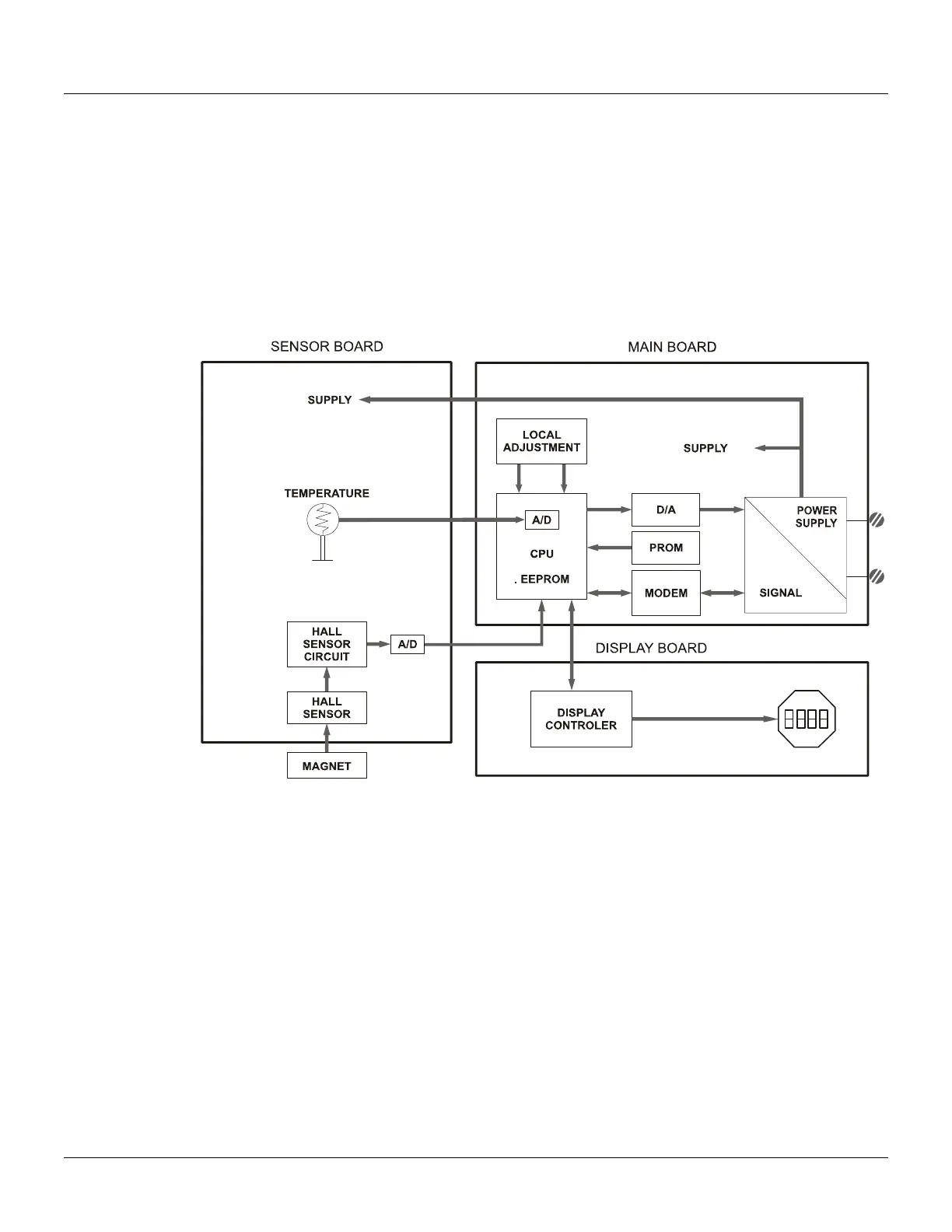
Functional Description – Electronics
Refer to the block diagram. The function of each block is described below.
Figure 2.1 - TP303 Block Diagram Hardware
Oscillator
This oscillator generates a frequency as a function of sensor capacitance.
Signal Isolator
The control signals from the CPU and the signal from the oscillator are isolated to avoid ground
loops.
Central Processing Unit (CPU), RAM, FLASH and EEPROM
The CPU is the intelligent portion of the transmitter, being responsible for the management and
operation of measurement, block execution, self-diagnostics and communication. The program is
stored in a flash memory for easy upgrade and saving data on power-down event occurrence. For
temporary storage of data, there is a RAM. The data in the RAM is lost if the power is switched off,
however the main board has a nonvolatile EEPROM memory where the static data configured that
must be retained is stored. Examples of such data are the following: calibration, links and
identification data.
Fieldbus Modem
Monitors line activity, modulate and demodulate communication signals; inserts and deletes start
and end delimiters, and check integrity of frame received.