K
Kristin BriggsAug 1, 2025
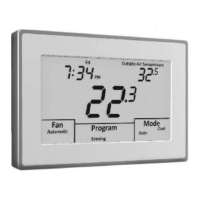
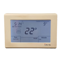
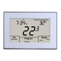
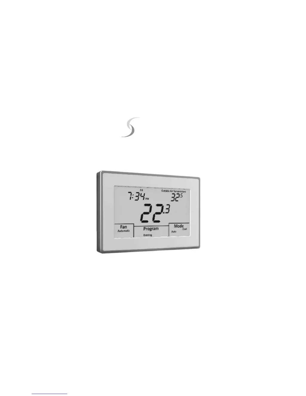
Why is the temperature display inaccurate on my Smart temp Apollo?
- HHolly PhillipsAug 1, 2025
If the temperature display on your Smart temp Control Panel is inaccurate, it might be due to air leaking from the wall cavity into the back of the thermostat. To resolve this, seal the hole where the wiring enters the subbase to prevent air infiltration. Also, external influences such as lamps or drafts might be affecting the temperature reading. Try moving lamps or other heat sources away from the thermostat.