2 OR 3 COOL (3 COOL ILLUSTRATED)
Switch Settings
Sw1 = OFF (Heat / Cool)
Sw2 = ON (Thermostat controls fan)
Sw3 = OFF (4 min anti cycle delay)
Sw4 = OFF (Leave OFF)
In Installer Menu, set 4EF = C (Cool Only) Set 17:R4 = C2 (A Relay = Cool 2)
Set 17:R4 = C3 (A Relay = Cool 3 and W = Cool 2)
Set 4:Fn = C (Cool Only Mode
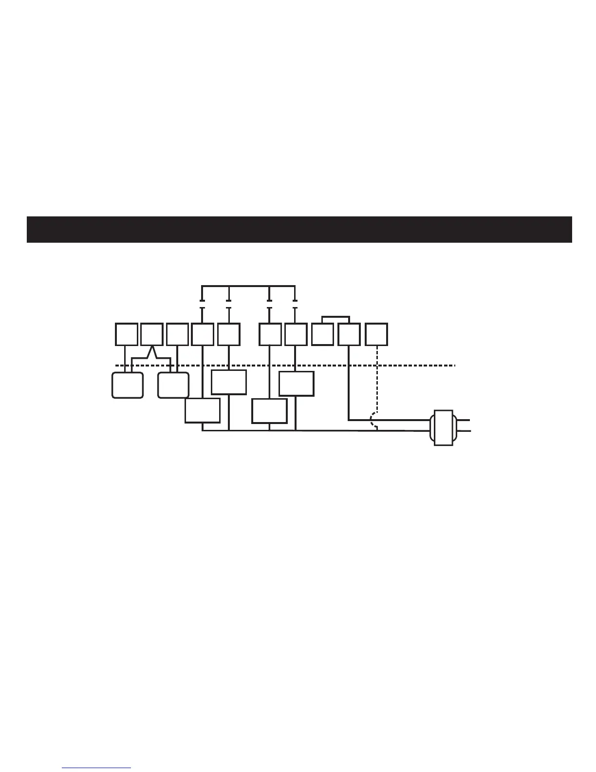
TYPICAL SYSTEM WIRING DIAGRAMS
17
SC
In
A
Y G
R
Com
C
COOL 1
RELAY
COOL 2
RELAY
COOL 3
RELAY
FAN 1
RELAY
LINE
24 V
W
Out
OPTIONAL
REMOTE SENSOR
TERMINALS
THERMOSTAT
EQUIPMENT
Factory Link
24C Optional
OUTDOOR
SENSOR
INDOOR
SENSOR