HFC6100LT Fan Controller User Manual Page 8 of 24
4.3 FAN CONTROLL MODE
4.3.1 AUTO MODE
Auto mode is activated by pressing , LED indicator beside the key is illuminating which confirms
this action.
4.3.2 AUTO CONTROL OUTPUT
4.3.2.1 ONE GROUP OF FANS CONTROLLED BY ONE GROUP OF SENSORS
Fan Automatic Control Setting:
a) The balanced running time is not enable, temp. sensor 1 controls the first group of fans and the
outlets of the first group of fans are (Output port 1 2 3 4);
b) The fan control curves (X1:60℃,Y1:0),( X2:70℃,Y2:1),( X3:80℃,Y3:2),( X4:90℃,Y4:3) ,
( X5:100℃,Y5:4);
c) The return difference value of sensor 1: 5℃;
d) 1#PWM output temp. sensor selects sensor 1.
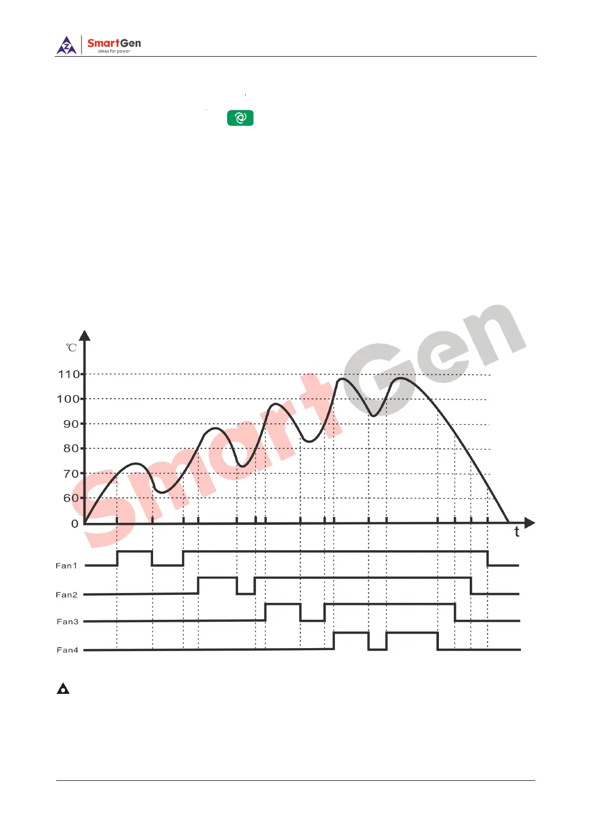
The logic graph of automatic running is shown as below:
Fig.2 – The Logic Graph of Automatic Control
NOTE: When balanced running time enables and meets the start condition, the fun with shortest running time will
output; when meets the stop condition, the fun with longest running time will shut down.
PWM1 will automatically output corresponding duty ratio according to the set PWM output curve.