EasyManuals Logo

Smartgen HFC6100LT User Manual

Smartgen HFC6100LT
24 pages
To Next Page IconTo Next Page
To Previous Page IconTo Previous Page
Page #11 background imageLoading...
Page #11 background image
HFC6100LT Fan Controller User Manual Page 11 of 24
6 CONNECTIONS
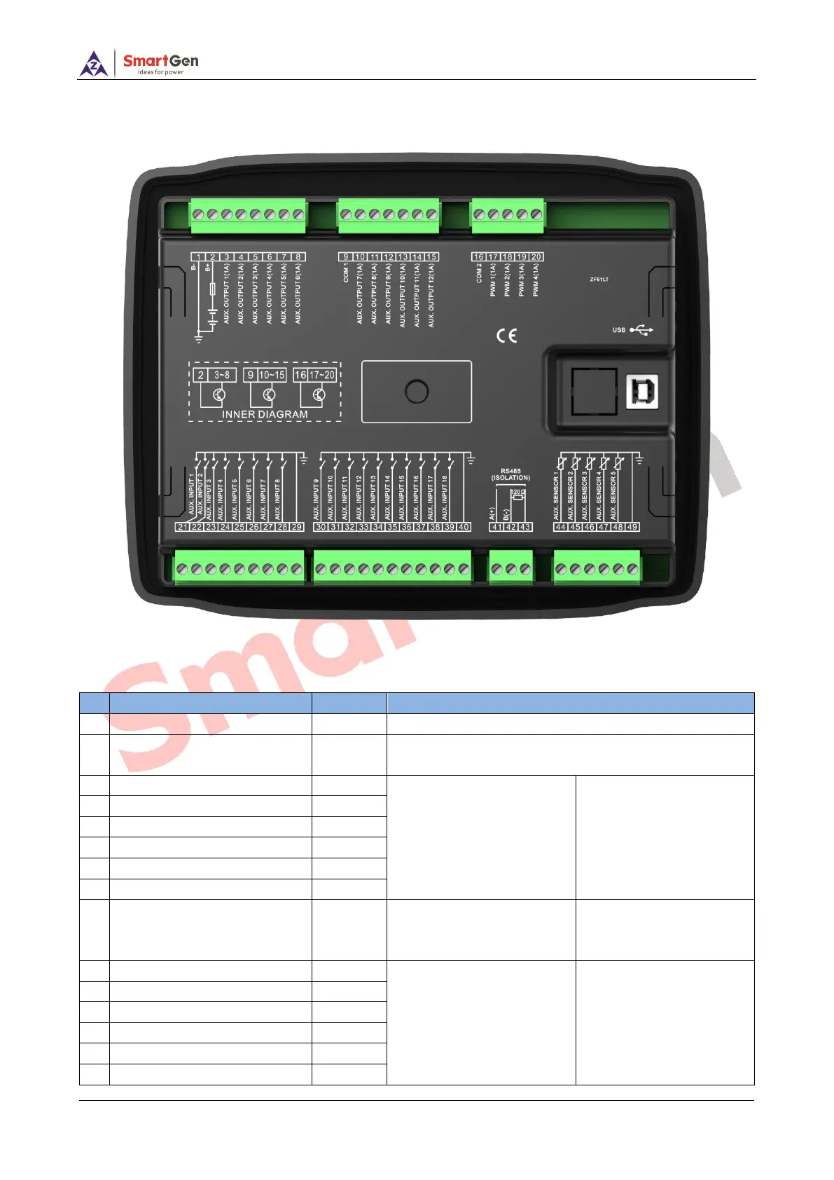
The rear panel of HFC6100LT is as below:
Fig.3 Controller Rear Panel Drawing
Table 6 Terminal Connection Description
No.
Function
Cable Size
Remark
1
DC input B-
1.5mm
2
Connect to negative of battery
2
DC input B+
1.5mm
2
Connect to positive of battery.
Max.10A fuse is recommended.
3
Aux. Output 1
1.0mm
2
B+ is supplied by 2 points,
Transistor output rated 1A.
Refer to Table 9
4
Aux. Output 2
1.0mm
2
5
Aux. Output 3
1.0mm
2
6
Aux. Output 4
1.0mm
2
7
Aux. Output 5
1.0mm
2
8
Aux. Output 6
1.0mm
2
9
COM1
1.5mm
2
Aux. output 7~12 common
ports, connect to positive of
battery.
10
Aux. Output 7
1.0mm
2
B+ is supplied by 9 points,
Transistor output rated 1A.
Refer to Table 9
11
Aux. Output 8
1.0mm
2
12
Aux. Output 9
1.0mm
2
13
Aux. Output 10
1.0mm
2
14
Aux. Output 11
1.0mm
2
15
Aux. Output 12
1.0mm
2

Questions and Answers:

Question and Answer IconNeed help?

Do you have a question about the Smartgen HFC6100LT and is the answer not in the manual?

Smartgen HFC6100LT Specifications

General IconGeneral
BrandSmartgen
ModelHFC6100LT
CategoryController
LanguageEnglish

Related product manuals