MGC100 Petrol Genset Controller User Manual Page 10 of 16
6 CONNECTION
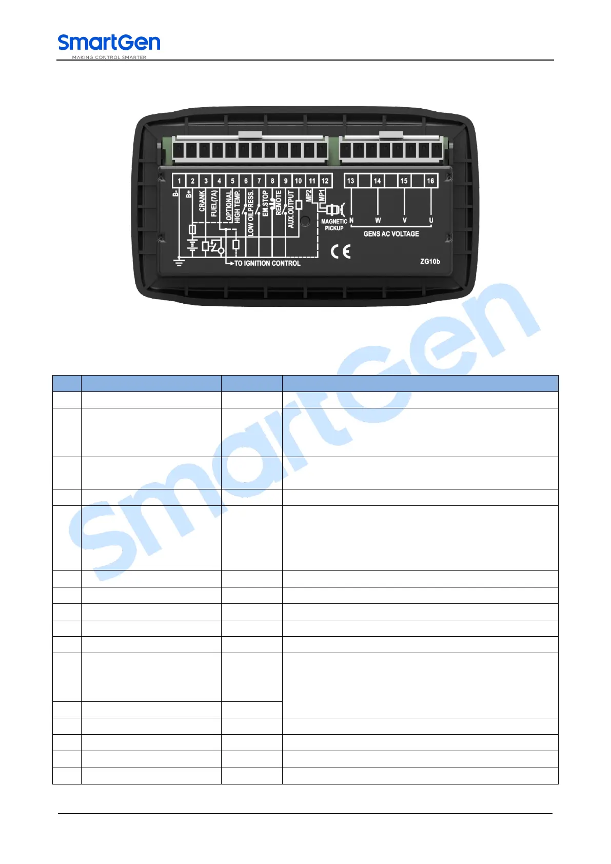
Fig.2 Rear Panel
Table 6 Terminal Connection Description
Connected with negative of starter battery.
Connected with negative of starter battery. If wire length
is over 30m, better to double wires in parallel. Max. 10A
fuse is recommended.
B+ power is supplied by terminal 2, rated 7A.
Connected with start coil of starter.
B+ power is supplied by terminal 2, rated 7A.
When this terminal short connected with (B+), it used as
diesel genset controller.
When this terminal connected with nothing, it used as
petrol genset controller.
Ground connected is active (B-).
Ground connected is active (B-).
Ground connected is active (B-).
Ground connected is active (B-).
B- power is supplied by terminal 1, rated 1A.
Magnetic Pickup 2
(B-) has already connected
with controller innerly.
Connected with Rotate Speed Sensor, shielding line is
recommended.
Connected with W phase (2A fuse is recommended).
Connected with V phase (2A fuse is recommended).
Connected with U phase (2A fuse is recommended).