HRX-OM-Q026
Chapter 3 Transport and Setting Up
3.3 Installation HRSH Series
3-20
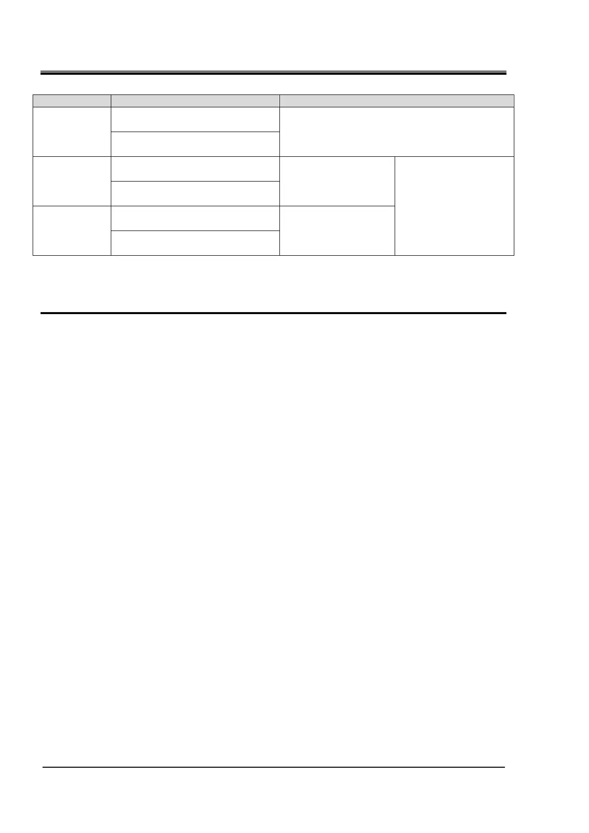
Table 3-6 Power supply, contact specifications
24 VDC ±10 % 500 mA MAX
*1
3
(Contact input signal 1)
- Run/Stop signal input
- External switch signal
input
*2
Switch the input on the
operation display panel.
Refer to the Operation
Manual Communication
Function for details.
11
(Common of contact input signal 1)
4
(Contact input signal 2)
- Run/Stop signal input
- Remote signal input
- External switch signal
input
*2
12
(Common of contact input signal 2)
*1: To use the power of the device, the total load current must be 500 mA or less.
If the load is 500 mA or more, the internal fuse will blow to protect the product and the alarm “AL21 DC
line fuse cut” will be generated. Refer to Chapter 6 Alarm Notification and Troubleshooting.
*2: Refer to “3.3.6 Wiring of external switch signal input.
1. Prepare the switch (power supply voltage: 24 VDC, contact capacity: 35 mA or more,
minimum load current: 5mA), and a signal cable. (See “Table 3-5 Signal cable)
 Loading...