HRX-OM-K003
Chapter 5 System Operation
HRW Series 5.3 Operation Screen
5.3.5 Status screen 4
*Status screen 4 is only indicated on HRW-HS
(pump inverter type).
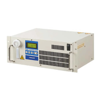
Figure 5-7 Status Screen 4
Table 5-6 Status Screen 4
Discharge flow rate of the circulating fluid
[Tips]
When using accessory [by-pass piping set] flow becomes total of flow on
customer side and flow on by-pass (*1).
5.3.6 Menu screen
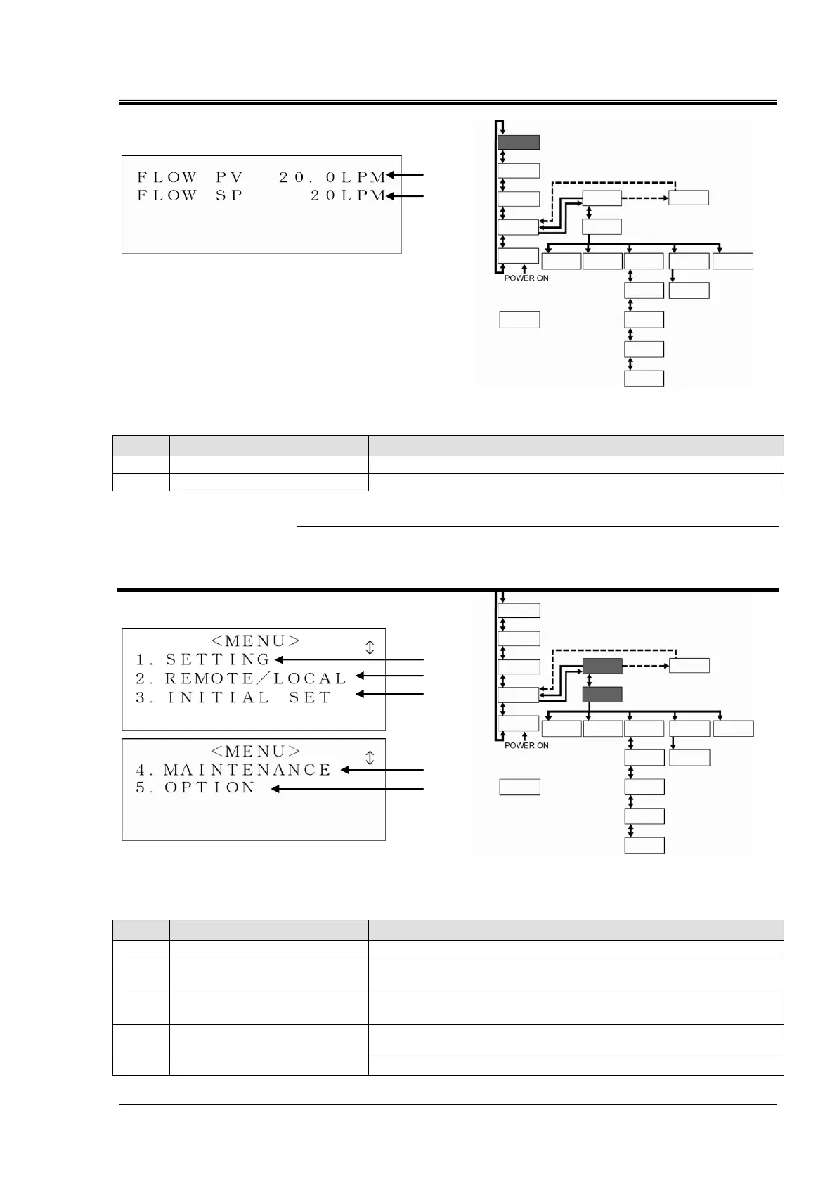
Figure 5-8 Menu Screen
Table 5-7 Menu Screen
Swicthes to the “Setting screen” with the press of the [ENT] key.
Swicthes to the “Mode Selection screen” with the press of the
[ENT] key.
Swicthes to the “Initial Setting screen 1” with the press of the
[ENT] key.
Swicthes to the “Maintenance screen 1” with the press of the
[ENT] key.
Swicthes to the “Option screen” with the press of the [ENT] key.
 Loading...