Programless Controller
LECP1 Series
e
r
t
y
u
i
o
!0
!1
!2
!3
!4
!5
!6
!7
!8
q
w
Mounting direction
Mounting direction
Ground wire
M4 screw
Cable with crimping terminal
Tooth lock washer
L
W
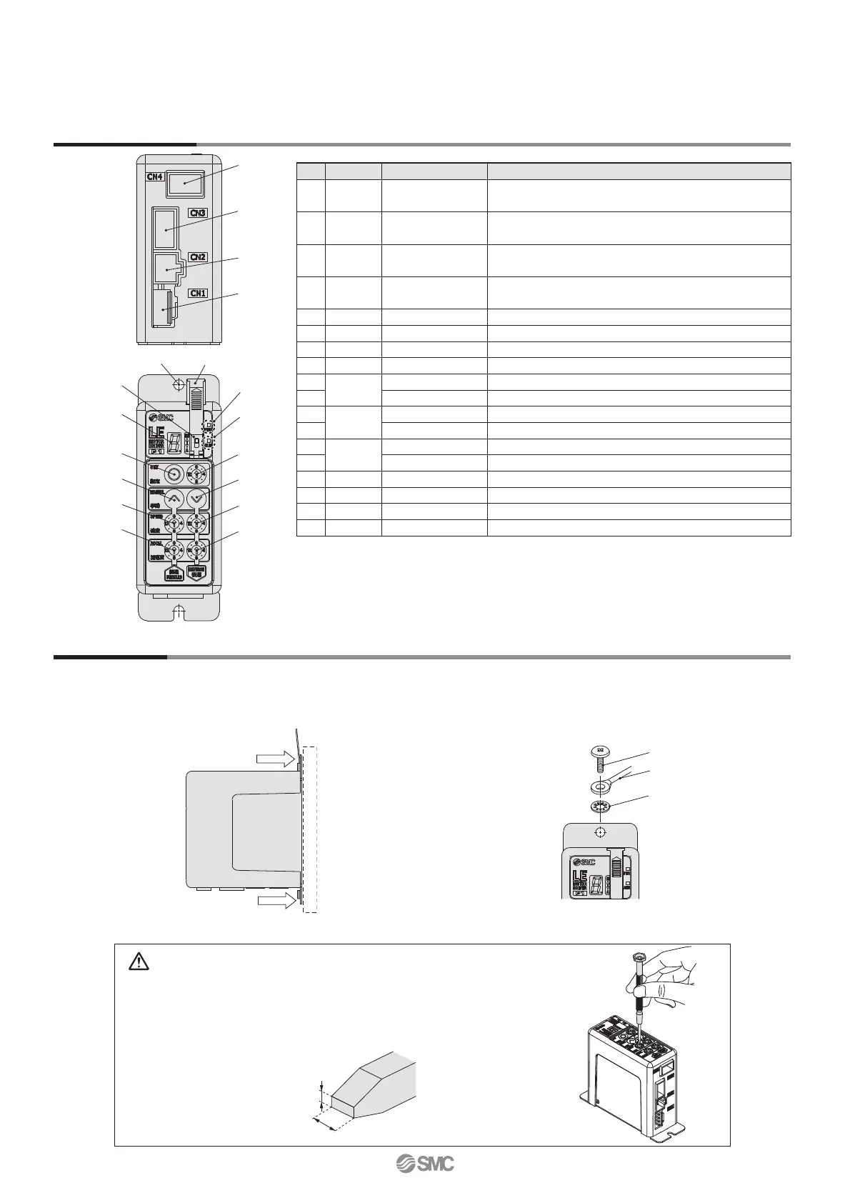
Controller Details
How to Mount
Caution
M4 screws, cable with crimping terminal and tooth lock washer are not included.
Be sure to carry out grounding earth in order to ensure the noise tolerance.
Use a watchmaker’s screwdriver of the size shown below when changing position
switch i and the set value of the speed/acceleration switch !1 to !4.
Size
End width L: 2.0 to 2.4 [mm]
End thickness W: 0.5 to 0.6 [mm]
Controller mounting shown below.
1. Mounting screw (LECP1-)
(Installation with two M4 screws)
2. Grounding
Tighten the bolt with the nut when mounting the ground wire
as shown below.
Magnifi ed view of the end
of the screwdriver
Controller
Note) When size 25 or more of the LE series are used, the space between the controllers should be 10 mm or more.
No. Display Description Details
q
PWR
Power supply LED
Power supply ON/Servo ON : Green turns on
Power supply ON/Servo OFF: Green fl ashes
w
ALM
Alarm LED
With alarm : Red turns on
Parameter setting : Red fl ashes
e
—
Cover
Change and protection of the mode switch
(Close the cover after changing switch)
r
—
FG
Frame ground (Tighten the bolt with the nut when mounting
the controller. Connect the ground wire.)
t
—
Mode switch Switch the mode between manual and auto.
y
—
7-segment LED
Stop position, the value set by i and alarm information are displayed.
u
SET
Set button Decide the settings or drive operation in Manual mode.
i
—
Position selecting switch
Assign the position to drive (1 to 14), and the origin position (15).
o
MANUAL
Manual forward button
Perform forward jog and inching.
!0
Manual reverse button
Perform reverse jog and inching.
!1
SPEED
Forward speed switch
16 forward speeds are available.
!2
Reverse speed switch
16 reverse speeds are available.
!3
ACCEL
Forward acceleration switch
16 forward acceleration steps are available.
!4
Reverse acceleration switch
16 reverse acceleration steps are available.
!5
CN1
Power supply connector
Connect the power supply cable.
!6
CN2
Motor connector Connect the motor connector.
!7
CN3
Encoder connector Connect the encoder connector.
!8
CN4
I/O connector Connect I/O cable.
2

 Loading...


