Programless Controller
LECP1 Series
CN4
1
2
3
4
5
6
7
8
9
10
11
12
13
14
Power supply 24 VDC
for I/O signal
Load
Load
Load
Load
Load
Load
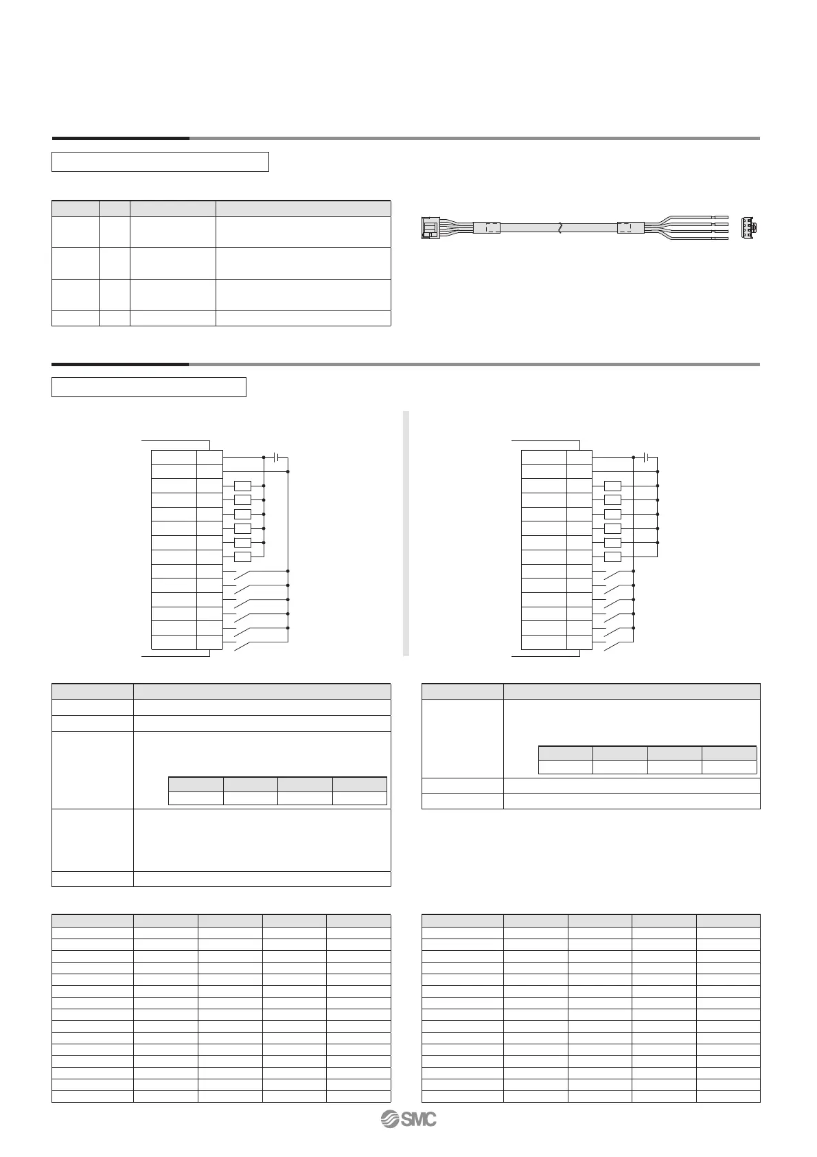
COM+
COM
OUT0
OUT1
OUT2
OUT3
BUSY
ALARM
IN0
IN1
IN2
IN3
RESET
STOP
COM+
COM
OUT0
OUT1
OUT2
OUT3
BUSY
ALARM
IN0
IN1
IN2
IN3
RESET
STOP
1
2
3
4
5
6
7
8
9
10
11
12
13
14
CN4
Power supply 24 VDC
for I/O signal
Load
Load
Load
Load
Load
Load
Wiring Example 1
Wiring Example 2
NPN
PNP
Parallel I/O Connector: CN4
∗ When you connect a PLC etc., to the CN4 parallel I/O connector, use the I/O cable (LEC-CK4-).
∗ The wiring should be changed depending on the type of the parallel I/O (NPN or PNP).
Power Supply Connector: CN1
∗ When you connect a CN1 power supply connector, use the power supply cable (LEC-CK1-1).
∗ Power supply cable (LEC-CK1-1) is an accessory.
Note) Signal of negative-logic circuit (N.C.)
Input Signal
Input Signal [IN0 - IN3] Position Number Chart
앪: OFF 앬: ON
Output Signal [OUT0 - OUT3] Position Number Chart
앪: OFF 앬: ON
Output Signal
CN1 Power Supply Connector Terminal for LECP1
Power supply cable for LECP1 (LEC-CK1-1)
Position number OUT3 OUT2 OUT1 OUT0
1
앪앪앪앬
2
앪앪앬앪
3
앪앪앬앬
4
앪앬앪앪
5
앪앬앪앬
6
앪앬앬앪
7
앪앬앬앬
8
앬앪앪앪
9
앬앪앪앬
10 (A)
앬앪앬앪
11 (B)
앬앪앬앬
12 (C)
앬앬앪앪
13 (D)
앬앬앪앬
14 (E)
앬앬앬앪
Return to origin
앬앬앬앬
Position number IN3 IN2 IN1 IN0
1
앪앪앪앬
2
앪앪앬앪
3
앪앪앬앬
4
앪앬앪앪
5
앪앬앪앬
6
앪앬앬앪
7
앪앬앬앬
8
앬앪앪앪
9
앬앪앪앬
10 (A)
앬앪앬앪
11 (B)
앬앪앬앬
12 (C)
앬앬앪앪
13 (D)
앬앬앪앬
14 (E)
앬앬앬앪
Return to origin
앬앬앬앬
Name Details
OUT0 to OUT3
Turns on when the positioning or pushing is completed.
(Output is instructed in the combination of OUT0 to 3.)
Example - (operation complete for position no. 3)
BUSY Outputs when the actuator is moving
∗ALARM
Note)
Not output when alarm is active or servo OFF
Name Details
COM+ Connects the power supply 24 V for input/output signal
COM− Connects the power supply 0 V for input/output signal
IN0 to IN3
•
Instruction to drive (input as a combination of IN0 to IN3)
•
Instruction to return to origin (IN0 to IN3 all ON simultaneously)
Example - (instruction to drive for position no. 5)
RESET
Alarm reset and operation interruption
During operation: deceleration stop from position at which
signal is input (servo ON maintained)
While alarm is active: alarm reset
STOP
Instruction to stop (after maximum deceleration stop, servo OFF)
Terminal name
Cable colour
Function Details
0V Blue
Common
supply (−)
M 24V terminal/C 24V terminal/BK
RLS terminal are common (−).
M 24V
White
Motor power
supply (+)
Motor power supply (+) supplied
to the controller
C 24V
Brown
Control power
supply (+)
Control power supply (+) supplied
to the controller
BK RLS Black Lock release (+) Input (+) for releasing the lock
OUT3 OUT2 OUT1 OUT0
OFF OFF ON ON
IN3 IN2 IN1 IN0
OFF ON OFF ON
4

 Loading...


