Programless Controller
LECP1 Series
(17.7)
(30.7)
Connector A
L (11)
(14.2)
(Terminal no.)
(14)
(18)
A1 B1
A6 B6
12
56
12
15 16
(Ø 8)
(Terminal no.)
Connector C
Controller side
Actuator side
(13.5)
(10)
Connector D
(14.7)
(17.7)
(30.7) L (11)
(14.2)
(14)
(18)
Connector A
(Ø 5.5)
(Ø 6.3)
(Terminal no.)
12
56
12
15 16
A1 B1
A6 B6
(Terminal no.)
Actuator side
Controller side
Connector C
Connector D
(14.7)
(13.5)
(10)
B1
(Terminal no.)
B6
A1
A6
B1
B3
A1
A3
(Ø 8)
(Ø 5.7)
(17.7)
(10.2)
(30.7) L (11)
(14.2)
(14)
(18)
Actuator side
Controller side
(Terminal no.)
Connector A
Connector B
Connector C
Connector D
(14.7)
12
56
12
15 16
(13.5)
10
B1
(Terminal no.)
B6
A1
A6
B1
B3
A1
A3
(Ø 5.5)
(Ø 6.3)
(Ø 5.7)
(17.7)(10.2)
(30.7) L (11)
(14.2)
(14)
(18)
Actuator side
Controller side
Connector A
Connector B
Connector C
Connector D
(14.7)
(Terminal no.)
12
56
12
15 16
(13.5)
(10)
Shield
Shield
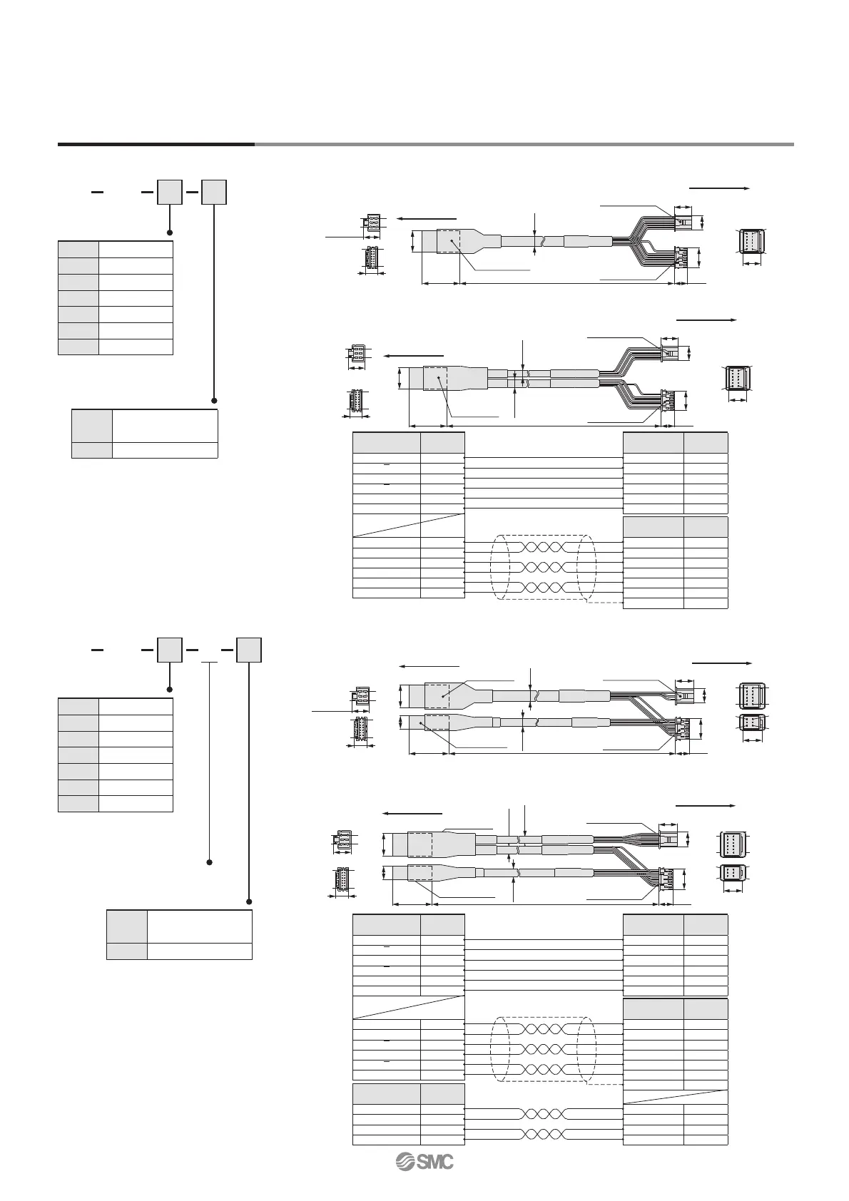
Options: Actuator Cable
[Robotic cable, standard cable for step motor (Servo/24 VDC)]
LE CP 1
Cable length (L) [m]
LE-CP- /Cable length: 1.5 m, 3 m, 5 m
1
3
5
LE-CP- /Cable length: 8 m, 10 m, 15 m, 20 m
(∗
Produced upon receipt of order)
8
A
B
C
∗ Produced upon receipt of
order (Robotic cable only)
Cable type
[Robotic cable, standard cable with lock and sensor for step motor (Servo/24 VDC)]
LE-CP- /Cable length: 1.5 m, 3 m, 5 m
1
3
5
LE-CP- /Cable length: 8 m, 10 m, 15 m, 20 m
(∗ Produced upon receipt of order)
8
A
B
C
LE CP 1 B
Cable length (L) [m]
With lock and sensor
∗ Produced upon receipt of
order (Robotic cable only)
Cable type
—
Robotic cable
(Flexible cable)
S
Standard cable
—
Robotic cable
(Flexible cable)
S
Standard cable
1
1.5
3
3
5
5
8
8
∗
A
10
∗
B
15
∗
C
20
∗
Cable colour
Connector D
terminal no.
Brown 12
Black 13
Red 7
Black 6
Orange 9
Black 8
—3
Red 4
Black 5
Brown 1
Blue 2
Cable colour
Connector C
terminal no.
Brown 2
Red 1
Orange 6
Yellow 5
Green 3
Blue 4
Signal
Connector B
terminal no.
Lock (+) B-1
Lock (−) A-1
Sensor (+)
Note)
B-3
Sensor (−)
Note)
A-3
Signal
Connector A
terminal no.
A B-1
A
A-1
B B-2
B
A-2
COM-A/COM B-3
COM-B/— A-3
Vcc B-4
GND A-4
A
B-5
A A-5
B
B-6
B A-6
Cable colour
Connector D
terminal no.
Brown 12
Black 13
Red 7
Black 6
Orange 9
Black 8
—3
Cable colour
Connector C
terminal no.
Brown 2
Red 1
Orange 6
Yellow 5
Green 3
Blue 4
Signal
Connector A
terminal no.
A B-1
A
A-1
B B-2
B
A-2
COM-A/COM B-3
COM-B/— A-3
Vcc B-4
GND A-4
A B-5
A A-5
B B-6
B A-6
1
1.5
3
3
5
5
8
8
∗
A
10
∗
B
15
∗
C
20
∗
6

 Loading...


