- 24 -
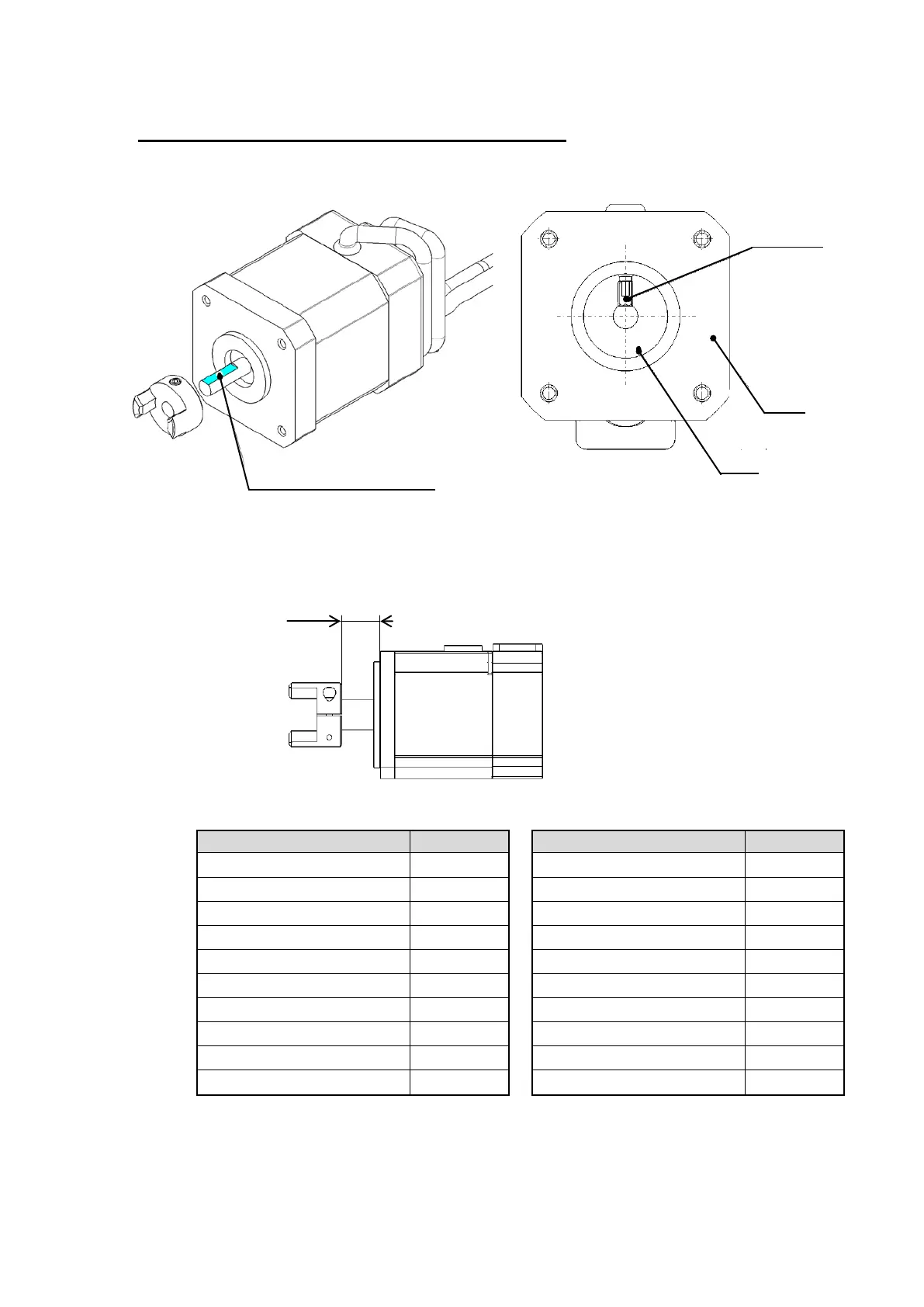
9-2. To reassemble, mount the hub in reversed order of removing. Points to be Noted for
Assembly.
Cautions 1):
Step motor (Servo /24VDC) and servo motor (24VDC)
When mounting the hub to the motor, make sure that the retaining screw of the hub
becomes the right angle for the D-cut of the motor shaft.
Cautions 2):
Make adjustment checking the mounting dimension L.
Apply adhesive to the retaining screw of the hub.
LEFS∗16∗∗
2.6
LEFS∗16(L/R)∗∗
3
LEFS∗25∗∗
4.3
LEFS∗25(L/R)∗∗
4
LEFS∗32∗
5.4
LEFS∗32(L/R)∗
5.6
LEFS∗40∗
5.1
LEFS∗40(L/R)∗
5.5
LEFS∗25(S/T/V)∗∗
12.4
LEFS∗25(L/R)(S/T/V)∗∗
8
LEFS∗32(S/T/V)∗∗
17.5
LEFS∗32(L/R)(S/T/V)∗∗
4.5
LEFS∗40(S/T/V)∗∗
17.5
LEFS∗40(L/R)(S/T/V)∗∗
4.5
LEFB25∗ (S/T/V)∗S
11
LEFB16∗T
2.5
LEFB32∗ (S/T/V)∗S
17.5
LEFB25∗T
5.3
LEFB40∗ (S/T/V)∗S
17.5
LEFB32∗T
3.3
For the replacement of the motor and hub (pulley), order the parts referring to the spare
parts list in the attachment.
Table 19. Hub (Pulley) fixing screws

 Loading...