-13-
No.PS※※-OMG0002-F
●The core of the corresponding colour shown in the following table is put into the pin of the number
stamped on the connector for sensor connection to the back.
Colour of cable core
PSE31
(Current input)
Number stamped
on connector
PSE30
(Voltage input)
Pressure sensor 2-wire type Pressure sensor 3-wire type
1 Brown (DC(+)) Brown (LINE(+)) Brown (DC(+))
2 N.C. N.C. N.C.
3 Blue (DC(
-
)) N.C. Blue (DC(
-
))
4 Black (OUT: 1 to 5 V) Blue (LINE(
-
)) Black (OUT: 4 to 20 mA)
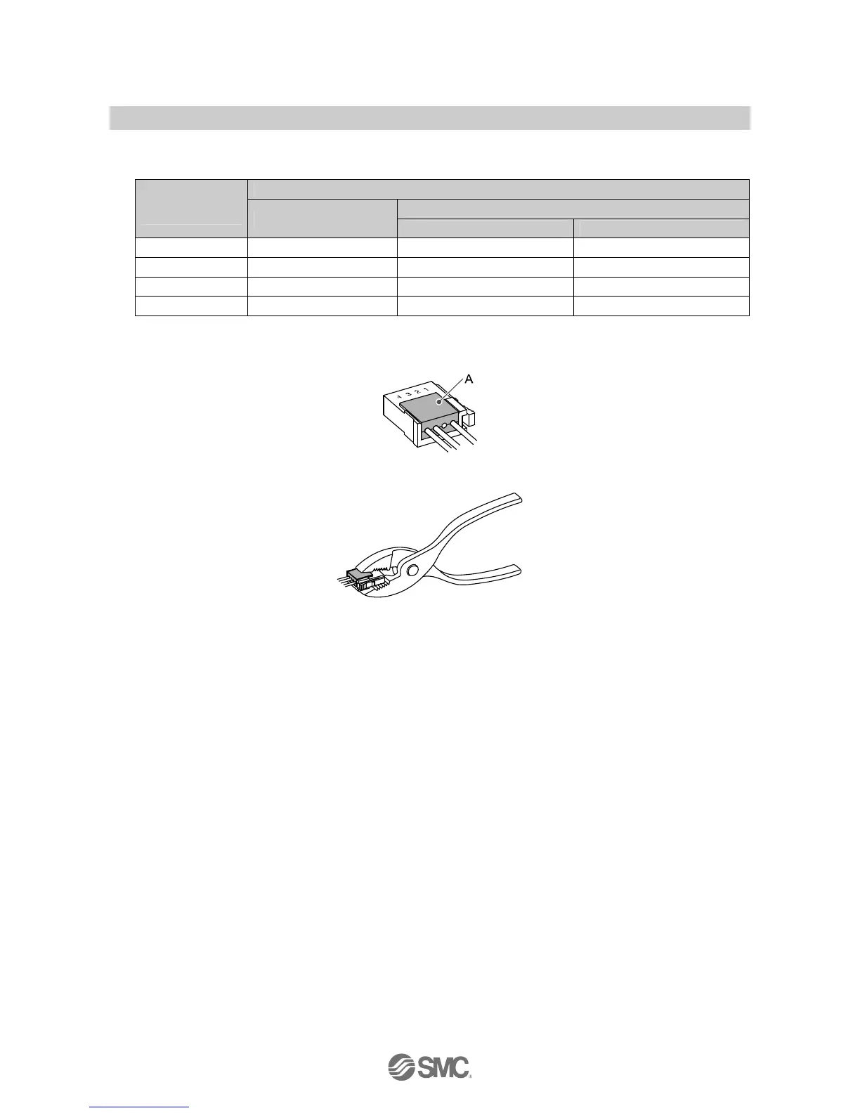
●It checks that the above-mentioned preparation work has been performed correctly, and A part shown in
right figure is pushed by hand and makes temporary connection.
●A part center is straightly pushed in by tools, such as pliers.
●Re-use cannot be performed once it connects the connector for sensor connection completely. When you
fail in the connection mistake of a core and a pin, or the plug of wire, please use the new connector for
sensor connection.