-14-
No.PS※※-OMG0002-F
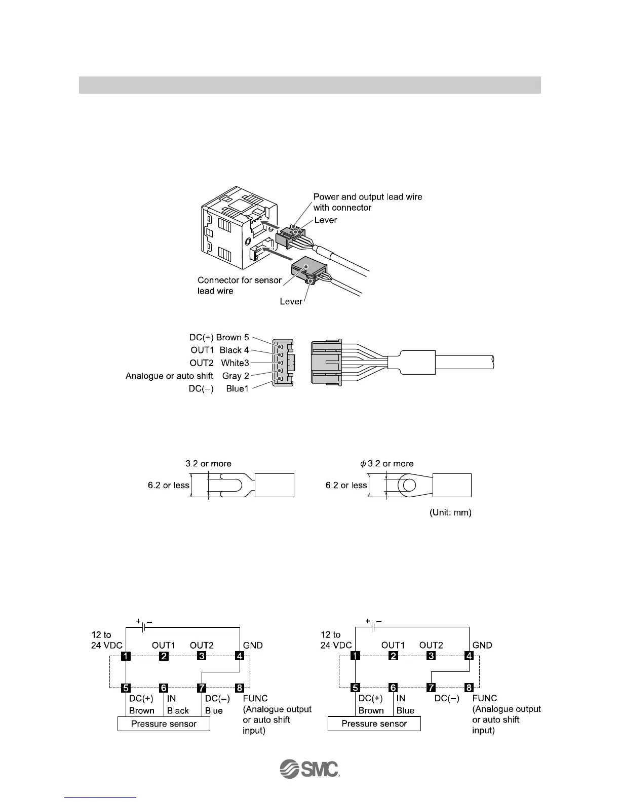
○Connector
Connecting/Disconnecting
●When connecting the connector, insert it straight onto the pin holding the lever and connector body
between fingers and lock the connector by pushing the lever claw into the square groove in the housing
until connector clicks.
●When disconnecting the connector, push down the lever by thumb to disengage the lever claw from the
square groove. Then pull the connector straight out.
Pin No. of the connector for power and output cable
<PSE3
T>
○Applicable crimping terminal dimensions
●The terminal screw is M3.
●If using the crimping terminal, follow the specifications below.
●Tighten the terminal screw at a torque of 0.3 to 0.35 Nm.
■Internal circuit and wiring example
○Wiring example
PSE3
T
(Voltage input, Current input: Pressure sensor
3-wire type)
PSE31
T
(Current input: Pressure sensor 2-wire type)