PTE-300-V
Sheet 10
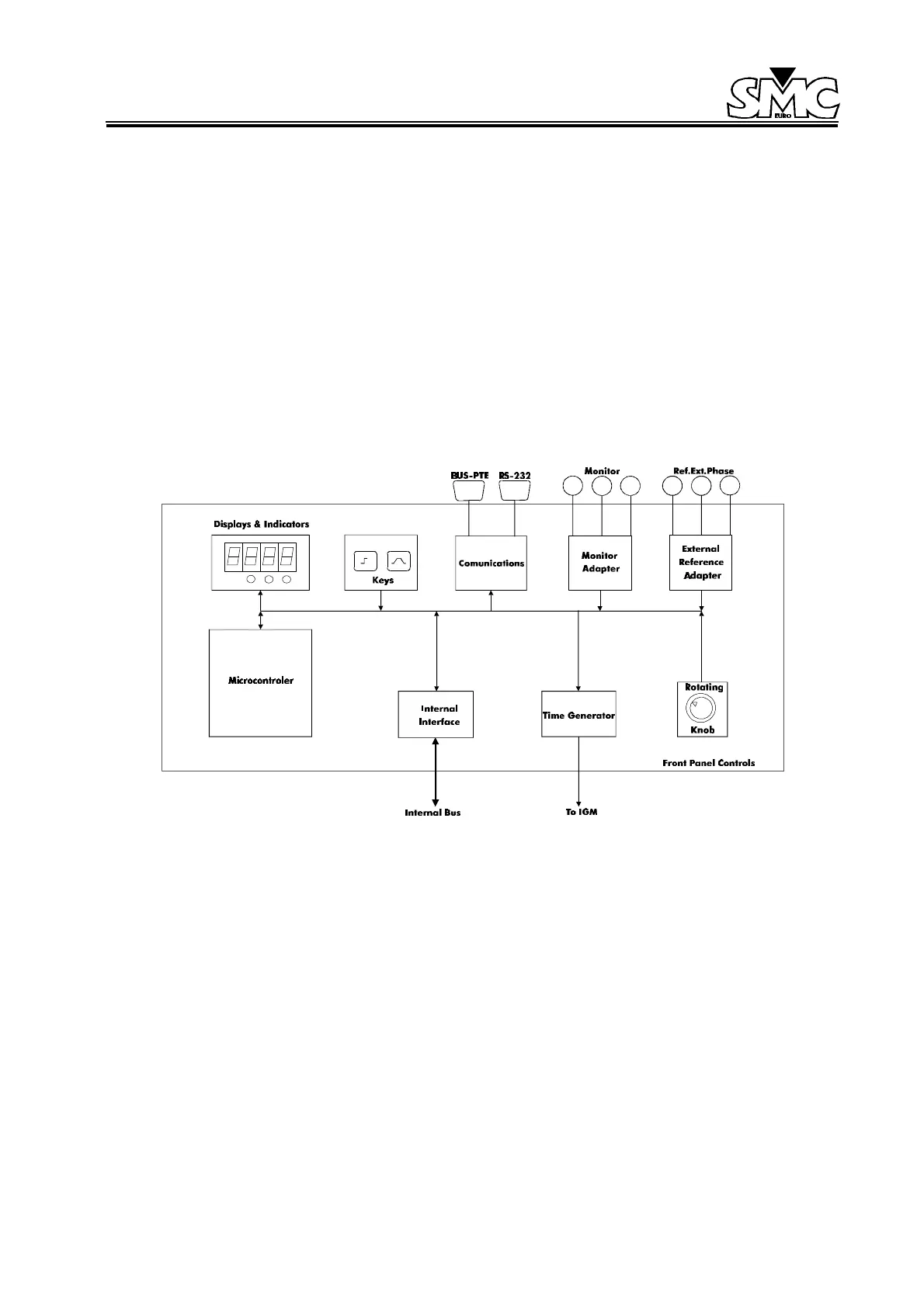
2.2. FRONT PANEL CONTROLS
Allows the user to communicate with the power output section of the unit in a manual way, or using a
software program. To achieve this, it has the following sections:
1. Displays and LED indicators: indicate the various selections made by the operator and the
status of the unit.
2. Press key controls: this is a membrane keyboard with acoustic feedback, in which the various
different functions available in the unit are selected.
3. Multi-turn control knobs: these are rotative pulse generators that are used to make the different
selections desired on the displays indicators, in an easy and fast manner.
4. Monitor taps: contain the circuits to detect the status of the signals applied in these taps.
Figure 3: Front Module
5. External Reference Taps: contain the circuits to synchronize the power outputs to the phase
and frequency signals connected to these taps.
6. Communications: the PTE units have the capability to communicate with some external control
devices by RS-232 (allowing the user for printing results and calibration from the PC) and by
BUS-PTE, for interconnection with PTE RANGE units and control of these by a PC.
7. Internal Bus Interface: establishes the communication between the Front Panel and the
Intelligent Generator Module, via the microprocessors included in both.
8. Time Generator: it generates the high accuracy time reference necessary to generate the
internal phase and frequency.
9. Output taps: these are the taps of the auxiliary voltage supply of 110 V ac, the power output
taps, and the tap to start an external timer.
 Loading...

