PTE-300-V
Sheet 13
• Power supply fuse holder: to reach these fuses, the cover must
be lifted as indicated in the drawing. There are two fuses: the
lower one is the active fuse and the one located above is the
spare fuse. The fuses are standard type, 5 x 20 mm, 10 A.
• Power supply switch: it has 2 positions, ON/OFF. The unit is
disconnected when the red mark of the switch is visible.
3.1.2. FIXED 110 V c.a. VOLTAGE SUPPLY
This output is located in the lower central section to the right of the power supply switch. It consists of
2 black taps.
This output is always active when the unit is switched on. The taps have a distance of 19 mm which
is the standard two-pole plug size.
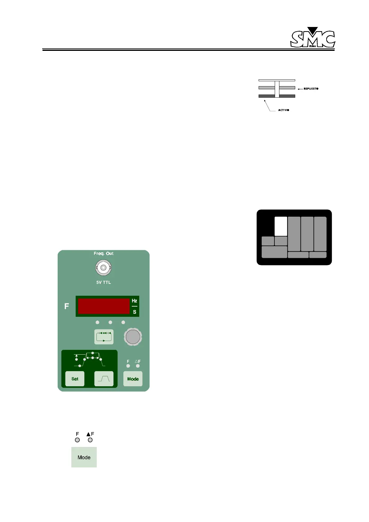
3.2. FREQUENCY SECTION
This section is located on the left-hand side of the unit and is clearly
marked. Contains all the control knobs, keys, and LEDs necessary for
the operator to use the frequency functions described in this section.
Figure 6: Frequency Section
3.2.1. CONTROL KEYS AND KNOBS
3.2.1.1. Mode function
This key works in a sequential way, when this key is pressed the LEDs will indicate
the option selected. The two options are:
1. Normal frequency mode (F).
 Loading...

