PTE-300-V
Sheet 12
3. CONTROLS DESCRIPTION
This section describes one by one and in detail all of the controls, indicators, displays, and connection
taps on the front panel of the PTE-300-V. As well as the functions, marked indications and where they are
located will be shown in the figures.
To understand this clearly, sections will describe the controls, by their functions, and by their physical
position on the front panel. The different types of controls that you can find are classified as follows:
• KEY CONTROLS: this refers to the press key and rotating knobs.
• DISPLAY AND OPTIC INDICATORS: this refers to the LED indicators and the selection displays.
• CONNECTORS (TAPS): this refers to all taps (input and output), connectors, etc., which are
contained in the PTE-300-V. This section describes all the connectors that are incorporated in the
unit. All of them meet international safety standards and are easily identified with their
corresponding identification marks on the front panel.
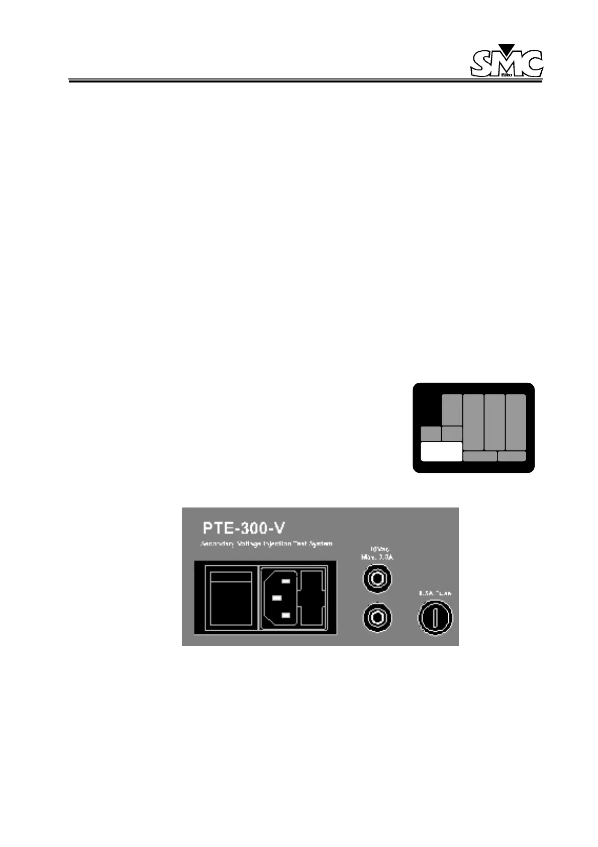
3.1. MAIN SUPPLY SECTION
3.1.1. MAIN VOLTAGE SUPPLY
The unit is supplied with SCHUKO type plug 2 poles with earth. Also
incorporated in the connector is a filter to avoid perturbations from the
main supply.
Figure 5: Main Supply
This is situated on the bottom left hand side of the unit and includes the following:
• Power supply with 2 poles and earth.
 Loading...

