PTE-300-V
Sheet 16
2. When flashing: this indicates that the ramp is active. When the Ramp key is pressed the
ramp will start. The LEDs will pass in successive order, indicating the state of the
equipment and the ramp in each moment.
3.2.2.3. Selection indicators
These three, 3 mm LEDs (red), indicate the digit to be regulated. Only one will
be lit and it will indicate the digit above it to be regulated
These LEDs are associated with the press key .
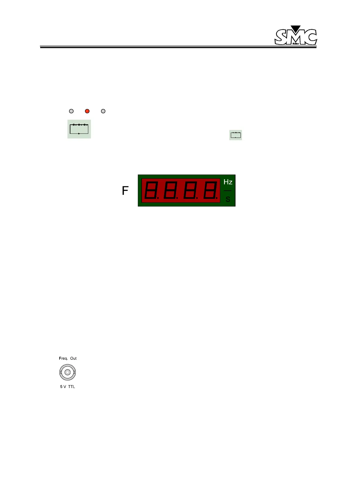
3.2.2.4. Selection display
The display is made up of 4 digits of 7 segments, red in color and 0.3 inches in height, which show
the selected value, and the units of the parameter selected which are located to the right of the
display.
It can work in three different modes:
• Hz (frequency).
• Hz/s (rate of change or slope).
• S (time duration in seconds).
When the output of the unit is not synchronized with this frequency generator, the display will
show “----” instead of the selection made, and all the controls in the frequency section will be
deactivated.
When working in the frequency ramp mode, and the Signal Monitor receives a signal (which
indicates a relay trip) the frequency display will hold the frequency value at the time of the trip
3.2.3. CONNECTORS: Auxiliary Frequency Output
This is a BNC conector that can be used to obtain a square form wave, TTL level, exactly
the same as the frequency being produced by the output, in real time.
 Loading...

