PTE-300-V
Sheet 21
• Current:
0 - 0.33 A
0 - 8 A
0 - 25 A
0 - 50 A
This key is associated with the 4 red LEDs with the ranges marked and the display in this
section.
d) ON/OFF LED indicator
This is a 3 mm, red LED that is situated below the corresponding press key.
It has two states:
• Not lit: indicates that there is no output (OFF).
• Lit: indicates that the output is on (ON).
• Not lit: indicates that there is no output (OFF).
This indicator shows the OUTPUT ACTUAL STATE. It can be either internally controlled by
the unit (for instance, Overload Alarm).
e) Digit selection indicator
These three, 3 mm LEDs (red), indicate the digit selection for regulation.
Only one will be lit, indicating the digit above it to be regulated.
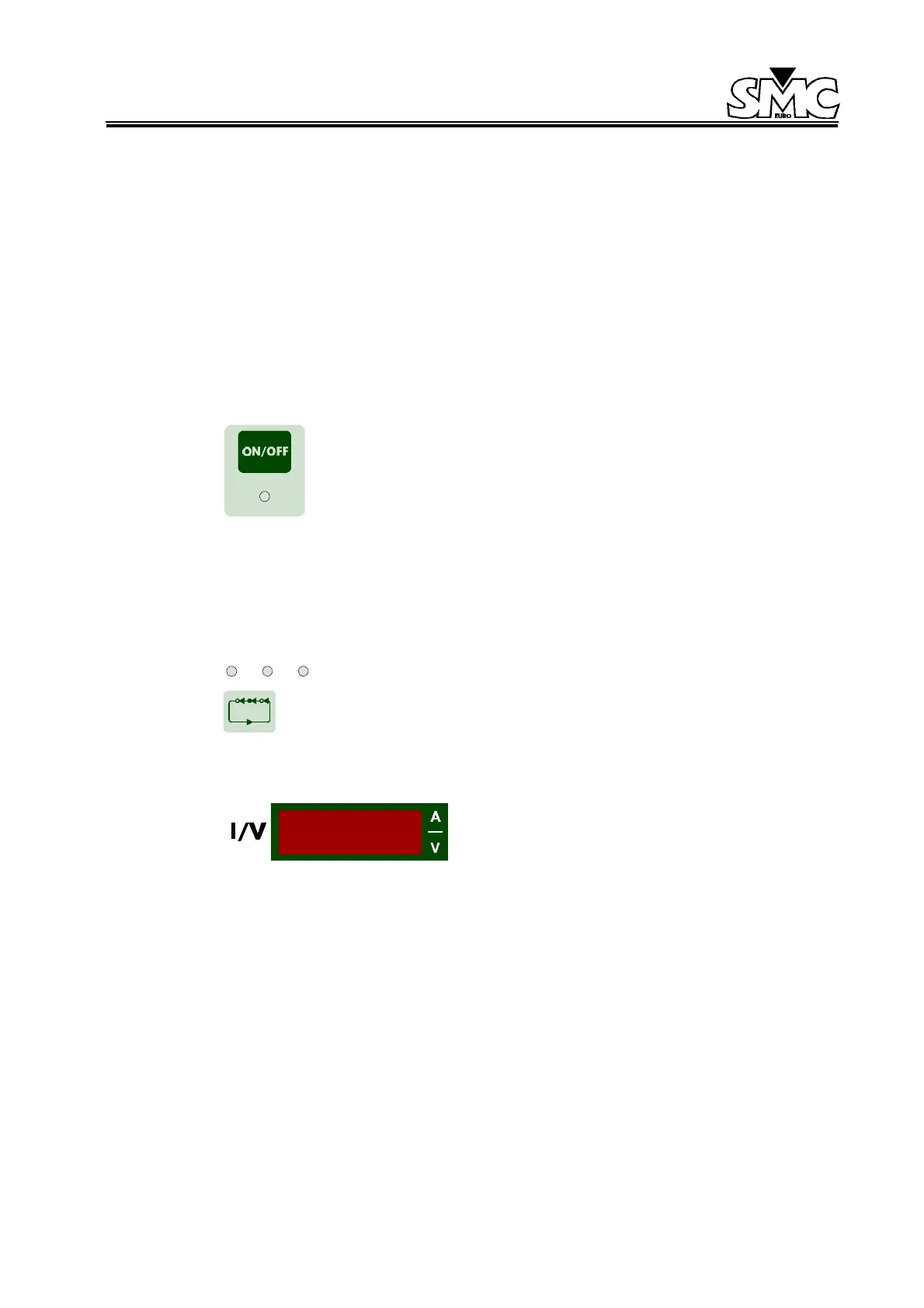
f) Level selection display
The display is made up of 4 digits of 7 segments, red
in color and 0.3 inches in height, which shows the
selected values and the corresponding units to the
selected parameter with three lightning indicators
located to the right side of the display.
There are two different parameters available:
• Voltage (V).
• Current (A).
In current and voltage, depending on the selected range, the decimal point will adjust
automatically. The V and A indicators will light up automatically when selected.
When the value in the display begins to flash, it indicates that the value selected and is not
in the output.
 Loading...

