Getting Started
2
18
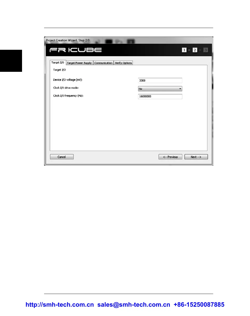
The number of tabs displayed in this window depends on the selected
target device; however, three tabs (“Target I/O”, “Target Power Supply”
and “Communication”) are always present and will be briefly discussed
below.
The first tab is “Target I/O”. The “Device I/O voltage” setting specifies
the voltage of the ISP lines. You should check the target board schematics,
or ask the board developer about this value. The allowed voltage also
depends on the selected target device.
The “Clock I/O drive mode” setting allows you to decide how the SxL04
ISP line is driven (the x index refers to the programming site; see “ISP
Connectors” on page 59). This line can be used as an auxiliary ISP line (to
provide a clock to the target device), as a generic I/O line, or as a high-
impedance output (no electrical driving). When used as output line (set to
high or low), it could be used, for example, to disable the external watchdog
circuit in the target board. When used as clock out, you can specify the
output frequency in the “Clock I/O frequency” field. We suggest leaving
this line floating (HiZ) when not used, in order to decrease electrical noise on
other ISP lines.
http://smh-tech.com.cn sales@smh-tech.com.cn +86-15250087885