21
USER’S MANUAL
www.smith-root.com
savings are not large.
• The resistance of an electrode varies in direct proportion to
water resistivity.
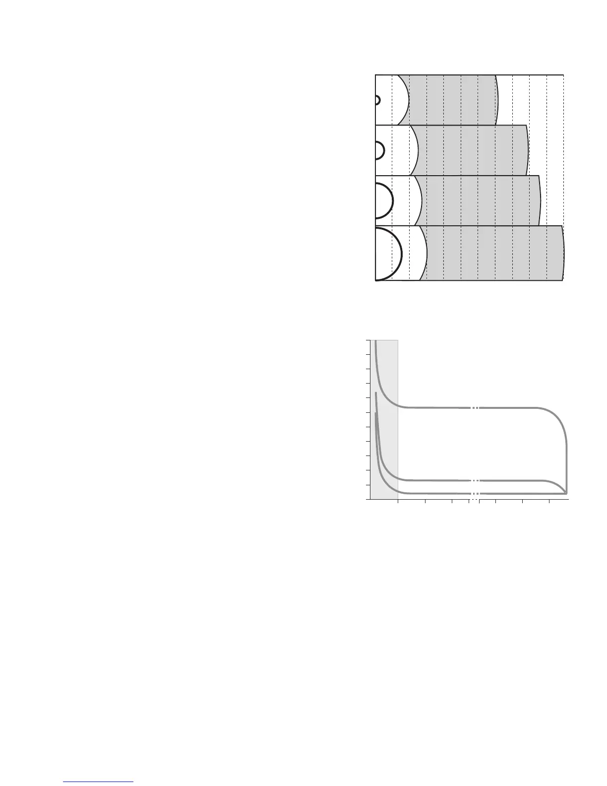
RING ELECTRODES
• Once spacing exceeds 10 radii, the distance between
electrodes is insignicant.
• The region affected by the electrode is limited to 5 to 10
radii.
• Electrode resistance is primarily dependent on electrode
radius, and varies in inverse proportion to radius.
• For ring electrodes, the cross section diameter of the ring
material is of little importance. If the ratio of cross section
diameter to ring radius is held constant, resistance varies
inversely with ring radius.
CATHODES
In electroshing it is desirable to have a high voltage gradient
around the anode, and a low voltage gradient around the
cathode.
Figure 8 shows variation of voltage, as a function of the
distance from the shing anode, for three types of cathode.
The required voltage is reduced by diminishing the resistance
of the cathode field. This compensates for the reduced
resistance so that the current does not vary. The power
consumption is directly proportional to the voltage used.
One advantage of a large cathode is that the risk of accidental
electrocution is much reduced. A large cathode has very low
potential with respect to the soil and the water around it. The
resistance between the cathode and the water is halved each
time the surface of the cathode is doubled. For example, a
100 square foot cathode would need another 100 square foot
added to pass from 9 to 4.5 ohm. However a cathode larger
than 100 square feet would be inconvenient to handle for
shore-side electroshing.
Figure 9 compares small and a large cathodes. With a standard
grid cathode, the anode voltage falls distinctly from 324 to
265 volts when using two anodes. However with a very large
wire netting cathode efciency falls only slightly from 324 to
302 volts when using two anodes.
For shore-side operations, the cathode surface presents the
least resistance when it is divided into several parts placed
several meters apart. An electrode is more effective when its
form is least concentrated. For example, a 3'x12' strip is more
effective than a square of 6'x6'.
Figure 10 illustrates the variation in both voltage and gradient
between the electrodes.
Whenever possible, the cathode should be placed in parts
of the stream that you do not wish to sh, or even in parts
Figure 7. Larger anodes increase the fishing area.
Figure 8.
Variation of voltage for three different kinds
of cathode
10cm
20cm
35cm
60cm
Electrode diameter
0.0 0.2 0.4 0.6 0.8 1.0 1.2 1.4 1.6 1.8 2.0 2.2
16.63m
2
12.57m
2
10.18m
2
6.16m
2
Distance from electrode centers (meters)
246 44 46 48
Distance from center of anode (meters)
00
100
150
200
250
300
350
400
450
500
550
50
Total voltage
Sufficient gradient zone
Cathode Indentical to anode: 600V, 6.3kW
0.5m2 grid cathode: 350V, 3.7kW
10m2 wire netting cathode: 310V, 3.2kW
anode
cathode
Figure 8. Variation of voltage for three kinds of anode.
INTRODUCTION TO ELECTROFISHING
 Loading...