3
USER’S MANUAL
www.smith-root.com
CONTROLS
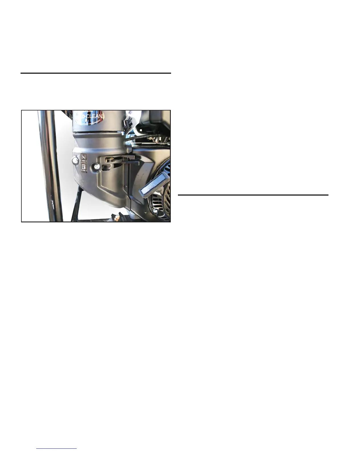
FUEL SHUT-OFF VALVE
The generator has one fuel shut-off valve. Make sure the valve is
open for proper operation. It is located directly below the choke
lever.
VOLTAGE VARIATION. All engines slow down when a load
is applied. When the electrical load on the generator is increased,
the engine speed drops. This results in a lower voltage when the
generator is loaded to its full capacity than when running unloaded.
FREQUENCY VARIATION. The AC frequency is around 60
cycles per second. The inevitable variations in engine speed
produce slight variations in the AC frequency. This has no
noticeable effect on the operation of motors, lights, and most
appliances. However clocks and other timing devices and will not
keep perfect time when used on generators.
MODIFICATIONS to the power supply that are not Smith-Root
authorized may impair the function and safety of the unit.
ELECTROFISHER CONTROLS
MODE
:
selects the type of output pulses. The DC output is
fast-rising slow-falling pulses. The DC pulse rate is selectable in
PULSES PER SECOND. For AC output the switches must be in
the AC position and in the 120 pps position. All other positions
will give a pulsed DC. The AC frequency is xed at 60 cycles per
second - however, the output is fast-rising slow-falling bipolar
pulses. Note the 2.5, 5.0, and 7.5 GPPs can produce AC output, but
AC is not available on the 9.0 GPP.
RANGE
:
selects the output voltage range, or switches the output
OFF.
PERCENT OF POWER: Allows the operator to smoothly vary
the output voltage and pulse width simultaneously, following the
positive half of a sine wave. It controls the area under the sine
curve of the output waveform. 50% is the peak voltage of the sine
curve, while 100% of range is the widest pulse width and greatest
area under the curve.
HIGH VOLTAGE
:
indicates when voltage is present on output
power terminals.
ENUNCIATOR VOLUME
:
controls the audio alarm that
indicates an output voltage.
OUTPUT CURRENT METER
:
shows the current flowing
between the anode and cathode in amps. LOW RANGE indicates
that the RANGE switch should be moved to the LOW position. For
7.5 and 9.0 GPPs follow the output table.
TIME IN SECONDS
:
records the actual shocking time. It counts
only when high voltage is applied. The timer helps evaluate capture
POWER SUPPLY CONTROLS
GENERATOR: Your GPP is powered by a specially manufactured
gas-powered generator. The generator is wound so that the output
voltages are taken directly from the generator, eliminating the need
for a transformer or voltage-doubler. The generator has a self-
excited revolving eld. This rotor connects directly to the engine
crankshaft with a tapered t. The stationary Stator has a separate
excitation winding, and multiple windings to supply AC power.
12 VAC: terminals on the generator provide up to 500 watts of 12
volts AC power on each circuit. This will run 12 volt lights, or with
an external rectier will recharge batteries. The 5.0, 7.5 and 9.0
GPP have two output circuits.
ENGINE: This instruction book covers mainly the electrosher
and the generator, but not the engine. Please read all instructions
in the engine manufacturer’s manual. The engine manufacturer has
established an excellent worldwide service organization. Engine
service is probably available from an authorized engine dealer near
you: check your Yellow Pages.
ENGINE GOVERNOR: The engine must be run at 3600 rpm
to supply the power it was designed to produce. The governor
on the engine holds the speed as nearly constant as possible. The
governor is set at the proper speed in the factory. Do not adjust the
governor without proper tools.