20
GPP ELECTROFISHER
USER'S MANUAL
© 2011 Smith-Root, Inc. Vancouver, WA - USA • Rev. 10
Contents
Introduction ........................................................................ 1
Unpacking .......................................................................... 2
Choosing a Location .......................................................... 2
Attaching Battery Leads .................................................... 2
Fuel Shut-Off Valves .......................................................... 3
Power Supply Controls ...................................................... 3
Electrosher Controls ........................................................ 3
Electrosher Connections .................................................. 4
Operating Procedure .......................................................... 4
Typical Hookups ................................................................ 5
Maintenance ....................................................................... 6
Basic Troubleshooting ....................................................... 7
GPP Specications Spreadsheet ......................................... 8
GPP Parts Identication ..................................................... 9
Fan Installation Kit/Engine Anti-Vibration Mounting ..... 10
Generator Anti-Vibration Mounting ................................ 11
Electrosher Control Panel .............................................. 12
Electroshing Safety ...................................................... 14
Preventing Electrical Shock ............................................. 16
Planning For Safety .......................................................... 17
Do's & Don'ts .................................................................. 18
Introduction to Electroshing .......................................... 19
Types of Current .............................................................. 21
Electrode Design .............................................................. 22
Field Techniques .............................................................. 26
Electroshing Reference & Training Materials ............... 27
APPENDIX: ADVANCED TROUBLESHOOTING .. 28
Check Generator AC Voltages ................................. 29
Test for Continuity and High Voltage Output .......... 30
Check Connections, Brushes & Exciter ................... 31
Check Rotor Windings ............................................. 32
Check Stator Windings ............................................ 33
Test GPP Control Box .............................................. 34
Test GPP Control Box- Cont. .................................. 35
Flashing the Rotor .................................................... 36
Building a Test Load ................................................ 37
2.5-5.0 GPP Wiring Diag ......................................... 38
7.5 GPP Wiring Diag ............................................... 39
9.0 GPP Wiring Diag ............................................... 40
Items manufactured by companies other than Smith-Root carry the original manufactures warranty. Please contact
product manufacturer for return instructions.
All Smith-Root, Inc. manufactured products are covered by a one year warranty.
2011
ELECTRODE DESIGN
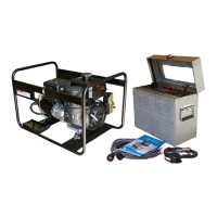
e way in which voltage and current distribute around
electrosher electrodes is complex. Figure 4 shows the
eld pattern created by a pair of closely spaced ring
electrodes, and the voltage gradient between them.
Note that the current density and voltage gradient are
highest near the electrodes.
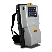
e dimensions of the electrodes are very important
in determining the voltage distribution around elec-
trosher electrodes. Figure 5 compares a 10cm and a
20cm ring anode carrying 200 volts in open water. e
cathode dimension is considered to be innite. Note
that the 20cm anode reaches out much further, produc-
ing a 33 volt potential at 1.2 meter. But the 10cm anode
produces the same potential at only 0.6 meter from the
electrode.
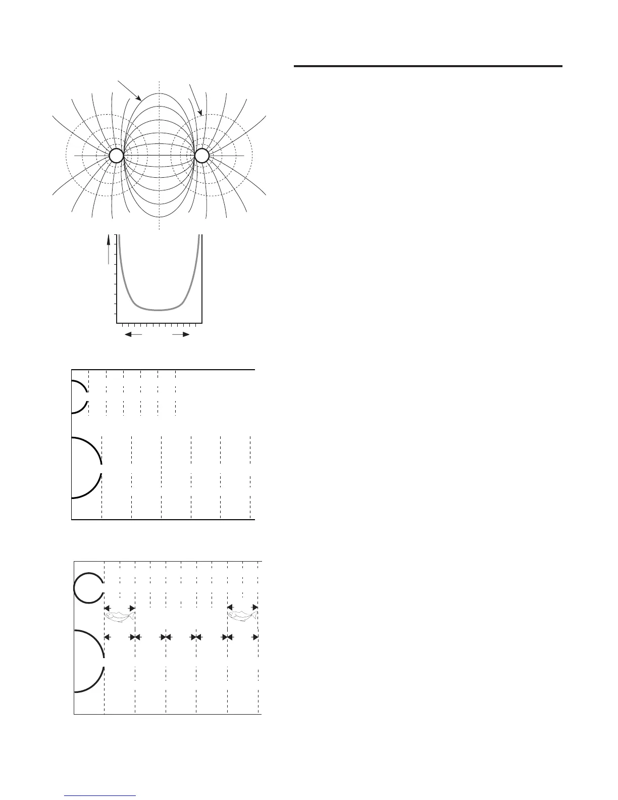
Figure 6 further illustrates the effect of electrode diameter.
The voltage is applied head-to-tail to a 20cm long sh. The
applied voltage is 200 volts with 10cm and 20cm diameter
ring-electrodes. Note that the 20cm electrode reaches out
farther, producing 7 volts head-to-tail between 1.0 and 1.2
meter from the electrode; as opposed to only 4 volts for the
smaller electrode at the same distance. Note also that the
voltage the fish receives closer to the electrode is less for
the larger electrode (100 volts instead of 144 volts). Larger
electrodes thus offers two advantages: greater range, and
lower maximum gradient.
One drawback is that a larger electrode also has greater
circuit loading, and thus draws more current for the same
voltage (twice as much for the double size electrode). Thus,
a larger electrode requires a larger generator. This dictates a
practical upper limit on electrode size for a given generator
and water conductivity. Except for this limitation, the larger
the electrode, the better the fishing effectiveness and the
easier it is on the sh.
Figure 7 shows that larger electrodes increase the fish
collection area. The shaded areas have a voltage gradient
between 0.12 and 1.2 volts per cm, and are suitable for
electroshing. The applied voltage is 300 volts.
ELECTRODE BEHAVIOR
• Larger electrodes have lower resistance, need more
current at given voltage, reach out farther, and have lower
maximum voltage gradient.
• Small electrodes pose a hazard to fish because of high
current density and voltage gradient.
• Electrodes placed farther apart use less current, but the
Figure 4. The field pattern, and the variation of gradient
between two electrodes.
Distance
Electrode Voltage
Gradient
Current lines Constant voltage lines
0.0 0.2 0.4 0.6 0.8 1.0
1.2
Distance from electrode centers (meters)
volts
1r 2r 3r 4r 5r
200 100 66 50 40
200 100 66 50 40 33
1r 2r 3r 4r 5r
33
10cm
20cm
volts
Figure 5. Comparison of two sizes of anode.
Figure 6. Comparison of effects of two sizes of anode.
0.0 0.2 0.4 0.6 0.8 1.0
1.2
volts
1r 2r 3r 4r 5r
200 100 66 50 40 33
200 100 66 50 40 33
1r 2r 3r 4r 5r 6r 7r 8r 9r 10r
28 25 22 20 18
100 44 16 10 7
134
4
volts
Distance from electrode centers (meters)
10cm
20cm
 Loading...