34
GPP ELECTROFISHER
USER'S MANUAL
© 2011 Smith-Root, Inc. Vancouver, WA - USA • Rev. 10
Contents
Introduction ........................................................................ 1
Unpacking .......................................................................... 2
Choosing a Location .......................................................... 2
Attaching Battery Leads .................................................... 2
Fuel Shut-Off Valves .......................................................... 3
Power Supply Controls ...................................................... 3
Electrosher Controls ........................................................ 3
Electrosher Connections .................................................. 4
Operating Procedure .......................................................... 4
Typical Hookups ................................................................ 5
Maintenance ....................................................................... 6
Basic Troubleshooting ....................................................... 7
GPP Specications Spreadsheet ......................................... 8
GPP Parts Identication ..................................................... 9
Fan Installation Kit/Engine Anti-Vibration Mounting ..... 10
Generator Anti-Vibration Mounting ................................ 11
Electrosher Control Panel .............................................. 12
Electroshing Safety ...................................................... 14
Preventing Electrical Shock ............................................. 16
Planning For Safety .......................................................... 17
Do's & Don'ts .................................................................. 18
Introduction to Electroshing .......................................... 19
Types of Current .............................................................. 21
Electrode Design .............................................................. 22
Field Techniques .............................................................. 26
Electroshing Reference & Training Materials ............... 27
APPENDIX: ADVANCED TROUBLESHOOTING .. 28
Check Generator AC Voltages ................................. 29
Test for Continuity and High Voltage Output .......... 30
Check Connections, Brushes & Exciter ................... 31
Check Rotor Windings ............................................. 32
Check Stator Windings ............................................ 33
Test GPP Control Box .............................................. 34
Test GPP Control Box- Cont. .................................. 35
Flashing the Rotor .................................................... 36
Building a Test Load ................................................ 37
2.5-5.0 GPP Wiring Diag ......................................... 38
7.5 GPP Wiring Diag ............................................... 39
9.0 GPP Wiring Diag ............................................... 40
Items manufactured by companies other than Smith-Root carry the original manufactures warranty. Please contact
product manufacturer for return instructions.
All Smith-Root, Inc. manufactured products are covered by a one year warranty.
2011
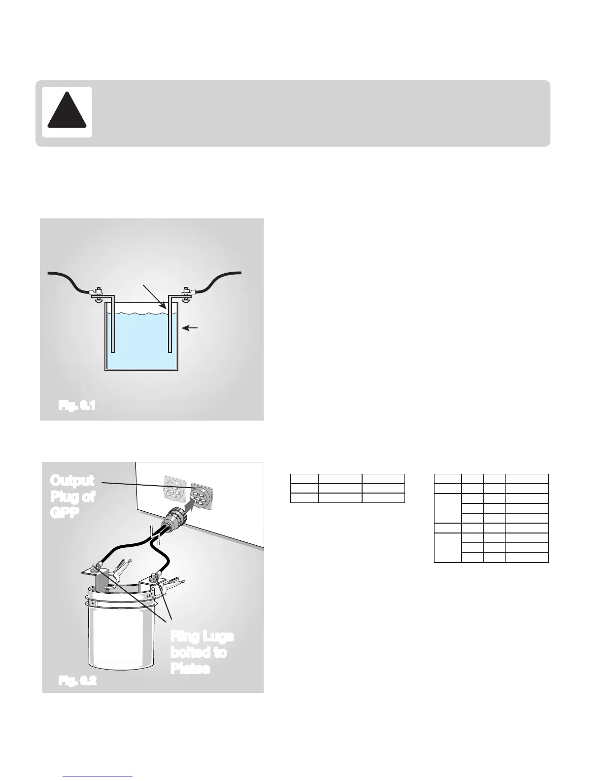
WARNING – KEEP ALL PERSONNEL CLEAR OF
TEST LOAD WHILE GENERATOR RUNNING.
• Construct a test load using a plastic bucket with the metal
handle removed (Fig. 9.1).
• Connect the test load to the GPP Electrosher as shown
(Fig. 9.2).
• Add tap water to the bucket.
• Set the “Mode Switches” on the GPP Control Box to AC &
120 PPS/ 60 AC.
• Start the generator.
• Control the GPP output with the “Emergency Shut Down”
switch or Foot switch.
• By turning the “Percent of Range” control up to 100% and
checking the amp meter on the GPP Control Box, the cor-
rect load can be determined. See below:
• The amp meter will increase to the maximum as you turn
up the “Percent of Range”.
• The load may be increased by slowly adding table salt to
the water in the bucket.
• If the load is too great for the range selected, the GPP will
operate erratically.
• If the amp meter starts to show a decrease in amps or is
erratic as the “Percent of Range” nears 100% the generator
is over-loading. The water may need to be changed, or
decrease the portions of electrodes immersed in the water.
Water
From Anode
Plastic Bucket
Aluminum Plate
From Cathode
Output
Plug of
GPP
Ring Lugs
bolted to
Plates
Maximum GPP Amperage (2.5 - 5.0)
Model High Low
2.5
5.0
8 Amps
16 Amps
4 Amps
8 Amps
7.5 120 V 170 V 62.5 A
31.3 A
20.8 A
10.4 A
240 V
360 V
720 V
340 V
500 V
1000 V
150 A60 V 85 V
75 A120 V 170 V
37.5 A240 V 340 V
18.8 A480 V 680 V
9.0
Maximum GPP Amperage (7.5 - 9.0)
Model DCAC Amperage
IMPORTANT! Danger! High Voltage is present during test load procedure.
Every effort should be made to keep all personnel away from test load bucket. It
may be necessary to form a barricade around testing area and post appropriate signs
warning of High Voltage.
Procedure 9: Build a Test Load
Fig. 9.1
Fig. 9.2
 Loading...