22
GPP ELECTROFISHER
USER'S MANUAL
© 2011 Smith-Root, Inc. Vancouver, WA - USA • Rev. 10
Contents
Introduction ........................................................................ 1
Unpacking .......................................................................... 2
Choosing a Location .......................................................... 2
Attaching Battery Leads .................................................... 2
Fuel Shut-Off Valves .......................................................... 3
Power Supply Controls ...................................................... 3
Electrosher Controls ........................................................ 3
Electrosher Connections .................................................. 4
Operating Procedure .......................................................... 4
Typical Hookups ................................................................ 5
Maintenance ....................................................................... 6
Basic Troubleshooting ....................................................... 7
GPP Specications Spreadsheet ......................................... 8
GPP Parts Identication ..................................................... 9
Fan Installation Kit/Engine Anti-Vibration Mounting ..... 10
Generator Anti-Vibration Mounting ................................ 11
Electrosher Control Panel .............................................. 12
Electroshing Safety ...................................................... 14
Preventing Electrical Shock ............................................. 16
Planning For Safety .......................................................... 17
Do's & Don'ts .................................................................. 18
Introduction to Electroshing .......................................... 19
Types of Current .............................................................. 21
Electrode Design .............................................................. 22
Field Techniques .............................................................. 26
Electroshing Reference & Training Materials ............... 27
APPENDIX: ADVANCED TROUBLESHOOTING .. 28
Check Generator AC Voltages ................................. 29
Test for Continuity and High Voltage Output .......... 30
Check Connections, Brushes & Exciter ................... 31
Check Rotor Windings ............................................. 32
Check Stator Windings ............................................ 33
Test GPP Control Box .............................................. 34
Test GPP Control Box- Cont. .................................. 35
Flashing the Rotor .................................................... 36
Building a Test Load ................................................ 37
2.5-5.0 GPP Wiring Diag ......................................... 38
7.5 GPP Wiring Diag ............................................... 39
9.0 GPP Wiring Diag ............................................... 40
Items manufactured by companies other than Smith-Root carry the original manufactures warranty. Please contact
product manufacturer for return instructions.
All Smith-Root, Inc. manufactured products are covered by a one year warranty.
2011
completely separated from the stream itself. The anode should
never be allowed to come close to where the cathode is located.
Boat Cathodes
Many aluminum electroshing boats use the boat hull as the
cathode and the boom electrodes as the anode. This is perfectly
safe as long as you never come in contact with the anode and
complete the electrical circuit. The National Safety Council in
their data sheet #1-696-85 does not recommend using the boat
hull as the cathode, but we have yet to hear of any accidents
occurring because of it.
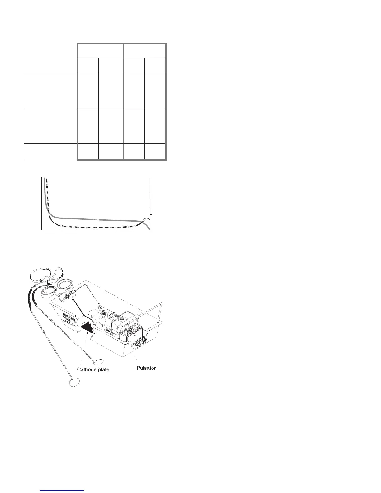
Figure 11 shows a Smith-Root tote barge designed for stream
wading operations. Note the large cathode plate attached to
the bottom of the berglass hull. The anode is a pair of ring
electrodes about 28cm (11") in diameter mounted on berglass
poles. With this arrangement, the resistance of the anode pair
is four times the cathode resistance. Thus, four times as much
voltage appears in the anode eld as in the cathode eld, and
consequently 80% of the applied voltage appears at each
electrode.
The situation could be further improved by enlarging the
cathode, but a point of diminishing returns is reached. Doubling
the cathode size would halve the cathode resistance and give
an 8 to 1 ratio between anode and cathode resistance. Now
88% of the voltage would appear at the anode. This is only
an 8% improvement, and is not worth the additional physical
problems associated with the larger cathode.
The SR-6 eld tested with two 28cm anodes and a voltage
of 240 volts, showed good fishing effectiveness in 400
microSiemens/cm conductivity with a current of 3 to 4 amperes.
In lower conductivities of 40 microSiemens/cm, a current of 1
to 1.5 amp is effective. This data may serve as a useful bench-
mark to judge whether a unit is operating under conditions such
that sh should be caught. If the electrical performance is close
to this reference point, and sh are not being caught, it is safe
to conclude there are few sh in the area.
35 99
Resistance ohms
of anode field90509050
between anode and cathode 125 85 99 59
Potential difference volts
between cathode and water 126 185 32 54
324 265 324 302
a. one
anode
Standard 0.5m
2
grid cathode
b. two
anodes anode anodes
Large wire-
netting cathode
Figure 9. Comparison of two sizes of cathode.
326450 450 356
3.6
1.62
5.9
2.38
3.6
1.28
6.0
2.15
between anode and water
c. one d. two
total
Current amps
Power kilowatts
35of cathode
Resistivity of the water in all cases=143 mho/cm
Figure 9. Comparison of two sizes of cathode.
Figure 11. Bottom mounted cathode plate on SR-6.
24 46 48
Total potential (volts)
Distance from center of anode (meters)
1.0
1.5
2.0
2.5
3.0
0.5
3.5
Anode
Cathode
Potential gradient (volts/cm)
Potential
Gradient
00
100
200
300
Figure 10. Variation of potential and gradient.
Figure 10. Variation of potential and gradient.


 To Next Page