USER'S MANUAL
© 2011 Smith-Root, Inc. Vancouver, WA - USA • Rev. 10
Contents
Introduction ........................................................................ 1
Unpacking .......................................................................... 2
Choosing a Location .......................................................... 2
Attaching Battery Leads .................................................... 2
Fuel Shut-Off Valves .......................................................... 3
Power Supply Controls ...................................................... 3
Electrosher Controls ........................................................ 3
Electrosher Connections .................................................. 4
Operating Procedure .......................................................... 4
Typical Hookups ................................................................ 5
Maintenance ....................................................................... 6
Basic Troubleshooting ....................................................... 7
GPP Specications Spreadsheet ......................................... 8
GPP Parts Identication ..................................................... 9
Fan Installation Kit/Engine Anti-Vibration Mounting ..... 10
Generator Anti-Vibration Mounting ................................ 11
Electrosher Control Panel .............................................. 12
Electroshing Safety ...................................................... 14
Preventing Electrical Shock ............................................. 16
Planning For Safety .......................................................... 17
Do's & Don'ts .................................................................. 18
Introduction to Electroshing .......................................... 19
Types of Current .............................................................. 21
Electrode Design .............................................................. 22
Field Techniques .............................................................. 26
Electroshing Reference & Training Materials ............... 27
APPENDIX: ADVANCED TROUBLESHOOTING .. 28
Check Generator AC Voltages ................................. 29
Test for Continuity and High Voltage Output .......... 30
Check Connections, Brushes & Exciter ................... 31
Check Rotor Windings ............................................. 32
Check Stator Windings ............................................ 33
Test GPP Control Box .............................................. 34
Test GPP Control Box- Cont. .................................. 35
Flashing the Rotor .................................................... 36
Building a Test Load ................................................ 37
2.5-5.0 GPP Wiring Diag ......................................... 38
7.5 GPP Wiring Diag ............................................... 39
9.0 GPP Wiring Diag ............................................... 40
Items manufactured by companies other than Smith-Root carry the original manufactures warranty. Please contact
product manufacturer for return instructions.
All Smith-Root, Inc. manufactured products are covered by a one year warranty.
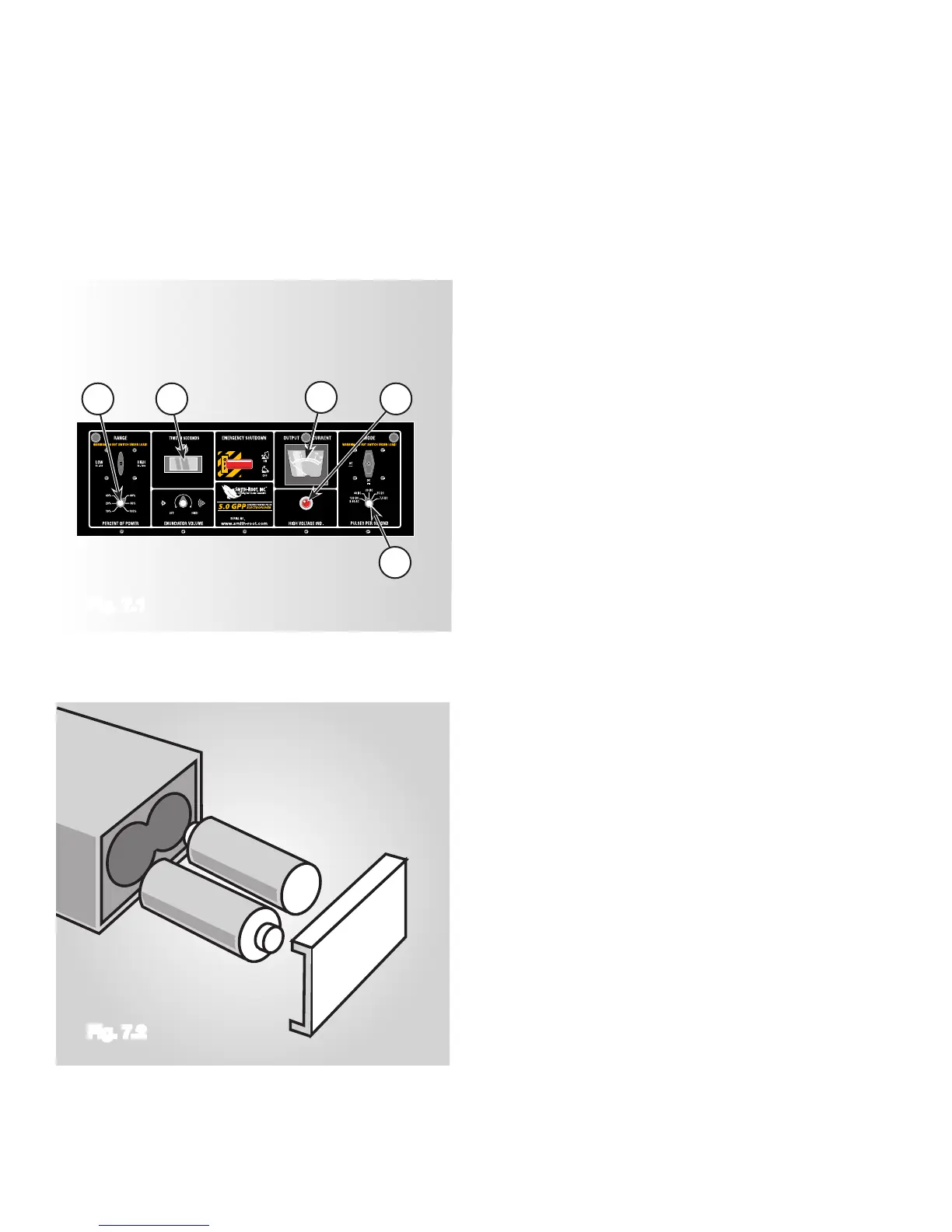
• Press foot switches.
• When the Red Light (See Fig. 7.1, A) is
illuminated, the “Current Meter” (See Fig. 7.1, B)
(See Fig. 7.1, C) should be counting.
Fig. 7.2).
• Set the “Percent of Range” to 50%.
120 PPS to 60 PPS. The amperage should drop by
half.
while the output is ON.
• Retest settings in the high range.
control box to Smith-Root, Inc.
ve years (See Fig. 7.2).
Fig. 7.1
Fig. 7.2
 Loading...