2
GPP ELECTROFISHER
USER'S MANUAL
© 2011 Smith-Root, Inc. Vancouver, WA - USA • Rev. 10
Contents
Introduction ........................................................................ 1
Unpacking .......................................................................... 2
Choosing a Location .......................................................... 2
Attaching Battery Leads .................................................... 2
Fuel Shut-Off Valves .......................................................... 3
Power Supply Controls ...................................................... 3
Electrosher Controls ........................................................ 3
Electrosher Connections .................................................. 4
Operating Procedure .......................................................... 4
Typical Hookups ................................................................ 5
Maintenance ....................................................................... 6
Basic Troubleshooting ....................................................... 7
GPP Specications Spreadsheet ......................................... 8
GPP Parts Identication ..................................................... 9
Fan Installation Kit/Engine Anti-Vibration Mounting ..... 10
Generator Anti-Vibration Mounting ................................ 11
Electrosher Control Panel .............................................. 12
Electroshing Safety ...................................................... 14
Preventing Electrical Shock ............................................. 16
Planning For Safety .......................................................... 17
Do's & Don'ts .................................................................. 18
Introduction to Electroshing .......................................... 19
Types of Current .............................................................. 21
Electrode Design .............................................................. 22
Field Techniques .............................................................. 26
Electroshing Reference & Training Materials ............... 27
APPENDIX: ADVANCED TROUBLESHOOTING .. 28
Check Generator AC Voltages ................................. 29
Test for Continuity and High Voltage Output .......... 30
Check Connections, Brushes & Exciter ................... 31
Check Rotor Windings ............................................. 32
Check Stator Windings ............................................ 33
Test GPP Control Box .............................................. 34
Test GPP Control Box- Cont. .................................. 35
Flashing the Rotor .................................................... 36
Building a Test Load ................................................ 37
2.5-5.0 GPP Wiring Diag ......................................... 38
7.5 GPP Wiring Diag ............................................... 39
9.0 GPP Wiring Diag ............................................... 40
Items manufactured by companies other than Smith-Root carry the original manufactures warranty. Please contact
product manufacturer for return instructions.
All Smith-Root, Inc. manufactured products are covered by a one year warranty.
2011
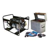
UNPACKING & SET-UP
UNPACKING
Carefully remove the GPP and its power supply from the shipping
container and examine closely for shipping damage. If any parts
are missing or the unit is damaged, notify the transportation
company and immediately le a claim for the amount of damage.
Record the model and serial number of your electrosher in the
spaces provided below:
Model Number
_______________________________________
Serial Number ________________________________________
When ordering parts, always include the power supply model and
serial number located on the unit’s nameplate. This is essential to
ensure the correct replacement part is shipped to you. Please keep
this manual and refer to it when making adjustments or ordering
parts. Additional copies are available for a nominal charge from
your distributor.
CHOOSING A LOCATION
In choosing the best location for your GPP, the following factors
should be taken into consideration:
FIRE HAZARDS: Locate the power supply at least 3 feet (1
meter) away from buildings or structures. Keep the power supply
away from ammable trash, rags, lubricants, and explosives. Do
not use the power supply near any forest, brush, or grassland
unless the exhaust system is equipped with a spark arrestor that is
effective. Have a re extinguisher accessible.
SECURITY: Choose a location where everyone, especially
children, can be kept away, to protect them from burns and
electrical shocks. Take precautions to prevent unqualified
personnel from tampering with or attempting to operate the power
supply.
SURFACE: Choose a level surface. If the power supply is tilted,
fuel spillage may result.
MOISTURE: Do not stand the unit in water or on wet ground.
Protect electrical equipment from excessive moisture that will
cause deterioration of the insulation and may result in short
circuits.
DIRT: Install the unit in a clean location. Abrasive materials such
as dust, sand, or lint cause excessive wear to both engine parts and
generator parts. Grass and leaves are a re hazard.
COLD: Engines should be located where the temperature does not
fall below freezing. Engines start easiest when they are not subject
to extreme cold.
HEAT: The temperature of the area where the engine is located
must not exceed 100°F because the engine is air-cooled. Where
natural ventilation is inadequate install a fan to boost circulation.
CONFINED SPACE: Restricted air ow can cause overheating
and damage the engine and generator. Operation in an enclosed
compartment is also a re hazard and is not authorized.
EXHAUST: Whenever an engine is used indoors, the exhaust must
be vented to the outside. Exhaust from a gas engine is extremely
poisonous, containing carbon monoxide, an invisible odorless gas
that can cause unconsciousness or death.
AUXILIARY WIRING: Use sufficiently thick insulated wire
to hook up to the auxiliary windings. The gauge depends on the
length of the wire, the voltage drop, and the amount and kind of
load. Consult a competent electrician and national and local codes.
GROUNDING: If grounding is called for in local codes, or radio
interference necessitates it, drive a 3/4 or 1 inch pipe into the
ground as close to the unit as possible. This pipe must penetrate
moist earth. To the pipe connect a ground clamp and run a No.10
wire from it to the battery negative terminal on the control panel,
or to the generator ground stud. Do not connect to a water pipe or
a ground used by a radio system. When used in boats, ensure that
generator frame is grounded to boat hull. This will prevent a shock
in the event of an electrical failure.