27
USER’S MANUAL
www.smith-root.com
IMPORTANT!: High voltages are present when generator is running. Only qualified
personnel should attempt high voltage measurements. We suggest forming a barricade around
the test area and posting appropriate high voltage warning signs.
SHUT DOWN GENERATOR!
Check all the connector pairs resistance to Generator ground.
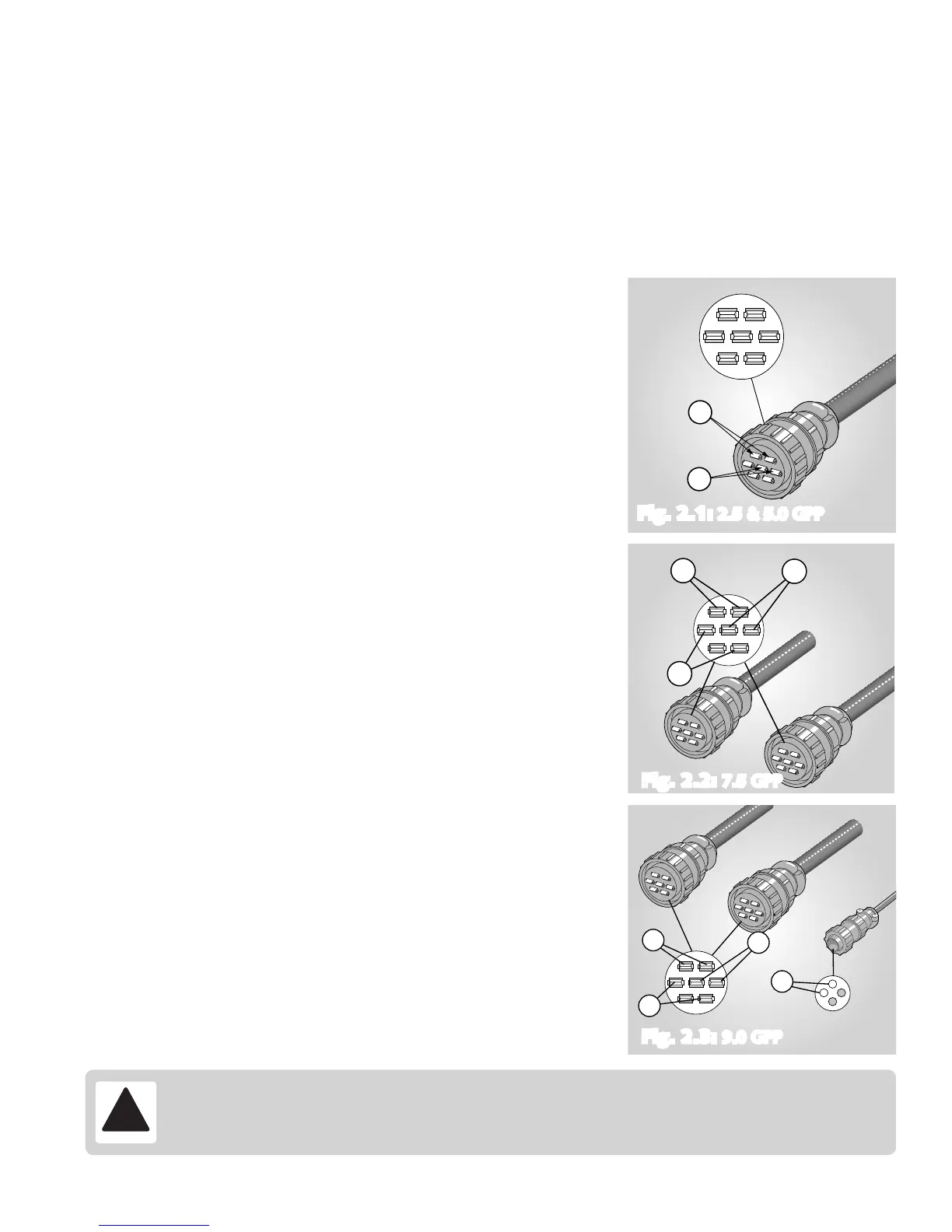
2.5 and 5.0 GPP: 1 & 2 / 3 & 4 (See Fig. 2.1)
7.5 GPP: 1 & 2 / 3 & 4 / 5 & 6 (See Fig. 2.2)
9.0 GPP: 1 & 2 / 3 & 4 / 5 & 6 (See Fig. 2.3)
All of the pairs should show open or high resistance
(>0.5 Meg-ohm).
• Next, check insulation between winding pairs.
If resistance measures low, the wire or generator insulation is bad.
If low resistance is measured, go to procedure 5.
• With generator running, check for High Voltage on generator connectors.
(See wiring diagrams at the end of this document).
2.5 and 5.0 GPP: Check each of the High Voltage
terminal pairs on the output connector for aprx. 360 Volts
RMS AC. Pairs: 1 & 2 and 3 & 4 (See Fig. 2.1).
7.5 GPP: Check each of the Voltage terminal pairs on both
of the output connectors for approximately 115 Volts
RMS AC. Pairs: 1 & 2, 3 & 4 and 5 & 6 (See Fig. 2.2).
9.0 GPP: Check each of the Voltage terminal pairs on both of the output
connectors for approximately 67 Volts RMS AC. Pairs: 1 & 2, 3 & 4 and 5
& 6 (See Fig. 2.3). Also, check for
115 Volts RMS AC on the smaller 2-pin connector.
If the Voltages are LOW or absent go to procedure 3.
If the Voltages are OK, go to procedure 6.
12
345
67
1&2
3&4
12
345
67
3&4
5&6
1&2
12
345
67
3&4
5&6
1&2
1&3
1
3
4
2
Procedure 2: Test for Continuity and High Voltage AC Output
Fig. 2.1: 2.5 & 5.0 GPPFig. 2.1: 2.5 & 5.0 GPP
Fig. 2.2: 7.5 GPP
Fig. 2.3: 9.0 GPP
PROBLEM: no output from gpp electrofisher (cont.)
ADVANCED TROUBLESHOOTING


 To Next Page