14 1061526 Rev. C VULCAN™ Generator Operations/Service Manual
Controls and Functions / Instructions for Use
Energy Delivery Tone
A tone sounds whenever RF energy is delivered.
Volume is adjustable using the volume control knob
on the control unit rear panel.
In Power Control Mode the tone is a steady sound
while RF energy is delivered.
In Temperature Control Mode the tone sounds
slowly while probe temperature is increasing. The
tone sounds more rapidly as the set temperature
is approached. The tone is rapid and steady when
the set temperature is reached and while it is held.
Any variation in tone speed signals the user that the
probe temperature is not at the target temperature.
Fault Tone
The fault tone sounds briefly during generator control
unit startup, and in the event of a warning or fault
condition. The volume of the fault tone cannot be
adjusted by the user.
Footswitch Connector
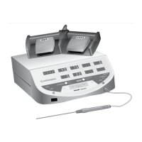
A dual, electrically-activated footswitch is provided
to control RF energy delivery. The blue COAG (right)
pedal is used with temperature-controlled probes
and with SET COAG in Power Control Mode. The
yellow CUT (left) pedal is used with cutting/ablation
probes in Power Control Mode.
Temperature Control Mode
Yellow CUT pedal – inactive
Blue COAG pedal – enables coagulation output with
temperature control
Power Control Mode
Yellow CUT pedal – enables cut output
Blue COAG pedal – enables coagulation output
Instructions for Use
1. Turn the control unit on using the on/off switch
on the rear panel. The generator will perform a
series of system self-tests to determine if it is
performing properly. If any of these tests fail, the
FAULT indicator will illuminate and a continuous
tone will sound. Contact Smith & Nephew
Customer Service if any system self-test fails.
Inspect the front panel displays for any system
indicator warnings or messages.
After completing the self-tests, the generator will
default to Stand-By Mode. All the displays on the
front panel will be blank and the generator will not
be able to deliver RF power.
2. Connect the selected Smith & Nephew probe
to the probe connector on the control unit front
panel. If the probe includes an integrated cable,
insert the cable connector with the thumb groove
up.
For probes without an integrated cable, connect
the probe to the extension cable. A “click” may be
heard. Tug gently on the extension cable to ensure
proper connection. Connect the other end of the
probe cable into the probe connector.
Note: ELECTROBLADE Resectors with a
two-prong Valleylab plug end can be plugged
into the ELECTROBLADE Adaptor for use with
the VULCAN™ Generator.
3. Verify that the selected probe’s name is
presented on the message display. The generator
software will recognize the probe type by reading
a sensor in the probe and will automatically
switch to the appropriate power output, MODE,
and setting for that specific probe.
WARNING: Burns to the surgeon’s hands
may be possible if a probe comes into
contact with a metal instrument or surface.
CAUTION: Check the probe and extension cable
connections for the presence of liquid before use
or whenever a probe is connected or disconnected
during a procedure. Liquid may enter the connection
during a procedure. ANY liquid can cause the
connections to short, resulting in erroneous probe
recognition or damage to the probe, cable, or
generator control unit.
CAUTION: Check the generator control unit’s LCD
message display to ensure that the proper probe
identification and settings are displayed prior to
beginning any procedure.



 To Next Page