8 1061526 Rev. C VULCAN™ Generator Operations/Service Manual
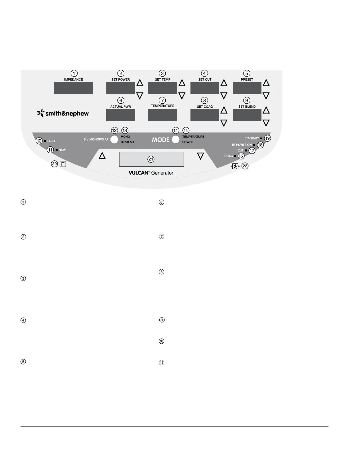
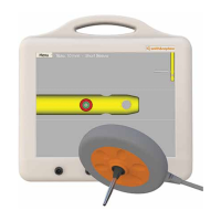
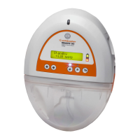
Front Panel Layout
IMPEDANCE Display
IMPEDANCE displays the impedance in ohms,
measured at the tip of the probe. Active in both
Temperature Control and Power Control Modes.
SET POWER Display with Up/Down Arrows
SET POWER displays the maximum probe power
output in watts, increased or decreased using
the SET POWER up/down arrows. Active only in
Temperature Control Mode.
SET TEMP Display and Up/Down Arrows
SET TEMP displays the target tissue temperature
in degrees Celsius (° C), increased or decreased
using the SET TEMP up/down arrows. Active only in
Temperature Control Mode.
SET CUT Display with Up/Down Arrows
SET CUT displays the maximum probe power output
in watts, increased or decreased using the SET CUT
up/down arrows. Active only in Power Control Mode
and the probe supports adjustment of SET CUT.
PRESET Display with Up/Down Arrows
PRESET displays the preset temperature and/or
power combination chosen and is adjustable using
the PRESET up/down arrows. Settings are displayed
as 1, 2, 3, etc. Active in Temperature Control and
Power Control Modes when the probe supports
adjustment of PRESET.
ACTUAL PWR Display
ACTUAL PWR displays the actual power in watts
delivered to the probe. Active only in Temperature
Control Mode.
TEMPERATURE Display
TEMPERATURE displays the actual temperature in
degrees Celsius (° C), measured at the tip of the
probe. Active only in Temperature Control Mode.
SET COAG Display with Up/Down Arrows
SET COAG displays the maximum probe power
output in watts, increased or decreased using the
SET COAG up/down arrows. Active only in Power
Control Mode and the probe supports adjustment
of SET COAG.
SET BLEND Display with Up/Down Arrows
The SET BLEND mode is inactive for all probes.
FAULT Indicator (Red Light)
FAULT illuminates when a fault condition is detected.
NEM Indicator (Green or Red Lights)
NEM illuminates with a green light when the NEM
circuit is correctly connected and with a red light
when the NEM circuit is incorrectly connected. NEM
will only illuminate when a monopolar probe is being
used.
Front Panel Layout
Figure 1. Control unit front panel