91061526 Rev. CVULCAN™ Generator Operations/Service Manual
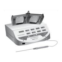
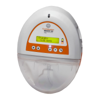
Front Panel Layout (continued)
BI / MONOPOLAR Button
The BI / MONOPOLAR button selects the appropriate
RF energy mode (monopolar or bipolar). The generator
selects the appropriate mode automatically based on
the probe type.
BI / MONOPOLAR Indicator
Either MONO (monopolar) or BIPOLAR is illuminated
to identify the appropriate probe type.
MODE Button
The MODE button selects the appropriate RF energy
delivery mode (Temperature Control or Power
Control).
MODE Indicator
Either TEMPERATURE (Temperature Control Mode)
or POWER (Power Control Mode) is illuminated to
identify the appropriate generator mode.
COAG Indicator (Blue Light)
COAG illuminates when the generator control unit is
delivering RF power and when the blue COAG (right)
footswitch is pressed.
CUT Indicator (Yellow Light)
CUT illuminates when the generator control unit is
delivering RF power and when the yellow CUT (left)
footswitch is pressed.
RF POWER ON Indicator (Green Light)
RF POWER ON illuminates when the generator control
unit is delivering RF power.
STAND-BY Indicator (Green Light)
STAND-BY illuminates when the generator control
unit is in Stand-By Mode.
Neutral (Return) Electrode Connector
Accepts a dual–pin connector specifically designed
for neutral electrode monitoring (NEM).
Message Display
Displays modes, probe type, alarms, warnings, or
fault messages.
Probe Connector
Accepts 8-pin Smith & Nephew temperature-
controlled, cutting, ablation, and hemostasis probes.
The Smith & Nephew VULCAN™ Extension Cable
(REF 7209693) may be used with the generator
control unit.