Mx37y_Technical_Description_ENG_v2.00.doc
16
─ Single- and three-phase electronic meters with built-in DLC
modem, GSM/GPRS modem or RS485 comm. interface
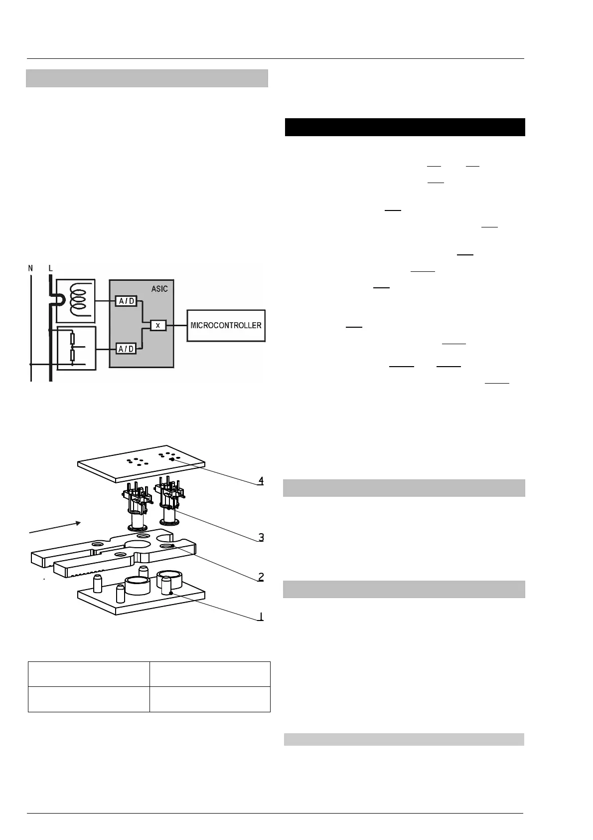
3.7. Metering system (MT37y)
Besides precision measurement of active energy and
demand in a wide metering and temperature range,
the metering system enables measurement of phase
voltages and currents.
Three (on request four) metering elements are built in
the meter. The current sensor is the Rogowski coil (a
current transformer with an air core), while a voltage
sensor is a resistive voltage divider. Signals of
currents and voltages are fed to the A/D converters,
and then they are digitally multiplied so that
instantaneous power is calculated. The instantaneous
powers are integrated and summed in a
microcontroller, as well as further processed.
Fig. 21: Metering element
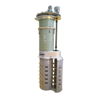
Explosion view of the Rogowski coil is shown in the
figure bellow.
I
Fig. 22: Explosion view of the Rogowski coil
1. Rogowski coil frame
3. Two Rogowski coils
(secondary winding)
2. Meter current loop
(primary winding)
4. Printed circuit board
The metering elements ensure excellent metering
properties:
1. Wide metering range
2. Negligible influence of disturbances and
influence quantities
3. Long-term stability so that meter re-
calibration is not required over its life
4. Long meter life and high reliability
4. Meter configuration
Meters consist of:
1. Metering system (items 2.4. and 3.7.)
2. Power supply unit (item 4.1.)
3. Microcontroller with non-volatile FRAM
memory (item 4.2.)
4. RTC – Internal real-time clock (Item 4.3.
)
5. LCD – Liquid Crystal Display in compliance
with VDEW specification (item 4.4.)
6. IR optical port (item 4.7.1.)
7. LEDs (item 4.5.)
8. Two push-buttons (Reset, Scroll) and one
push-button under the meter cover (Param)
(item 4.6.)
9. DLC modem (Mx371) (item 4.7.2.) or
GSM/GPRS (RS485) communication interface
(Mx372) (items 4.7.3. and 4.7.4.)
10. M-Bus communication interface (item 4.7.5.)
11. Impulse output or control optomos relay
(option)
12. Detectors (switches) of opening a meter and
terminal covers
13. M-Bus interface or switching device control
output (option)
4.1. Power supply unit
The power supply unit consists of a switcher, which
enables a meter to operate accurately in a wide
voltage range. It enables a meter to operate
accurately even when the meter is supplied from a
single phase and voltage in the network is only 80%
of the rated voltage.
4.2. Microcontroller with FRAM
The microcontroller acquires signals from the
metering element(s), processes them and calculates
values of measured energy. The results are stored in
energy registers for particular tariffs. It also calculates
demands and register maximum demand in billing
periods. The microcontroller also generates pulses
for the LED and the output pulses, enables two-way
communication via the optical port and the DLC
modem, and drives the LCD and the control outputs.
The microcontroller enables registration of a load-
profile and events into a log-book, as well.
4.2.1. Load-profile recorder
A load-profile recorder can be provided with up to two
channels. The following registration periods 15, 30
and 60 minutes or a daily value can be set. In each
channel up to sixteen objects can be registered of