Mx37y_Technical_Description_ENG_v2.00.doc
6
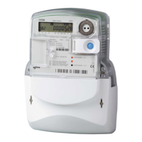
─ Single- and three-phase electronic meters with built-in DLC
modem, GSM/GPRS modem or RS485 comm. interface
DLC modem (Mx371): DLMS by IEC 62056–46
GSM/GPRS modem (Mx372); IEC 62056 – 46
RS485 Interface (Mx372); IEC 62056 – 46
Identification system; IEC 62056 – 61
COSEM organization of data: IEC 62056-53
M-Bus: EN 13757-2 and EN 13757-3
• OBIS data identification code: IEC 62056–61
• Auxiliary inputs / outputs:
Output for load control with a 6 A relay
Output for load control with an Optomos relay
Alarm input (low voltage)
M-Bus interface to which up to 4 gas, heat or
water meters can be connected (also a switching
device ZO340-D1)
Two impulse outputs or an output for control of
a switching device (ZO320-D1)
• Automatic configuration of an AMR system:
Meters are registered automatically into an
AMR system (Intelligent Network Management)
• Automatic meter setting into the repeater
mode (DLC repeater) :
Each meter can automatically enter into the
repeater mode and transmit data in both
directions, even with meters with which it can
not communicate directly.
Data transmission of max. 7 remote meters
which temporarily operate in the repeater
mode increases efficiency of communication
and distance between the meters and a data
concentrator.
• Call-back (Mx372):
The meter can perform a call and send a
message to the centre:
- After installation
- If a pre-defined alarm condition exists (e.g.
after Power Down/Up event)
- If a signal appears on the alarm input
• Programming:
Programming of the meter as well as Firmware
upgrade can be done locally (via an optical port)
or remotely (via GSM modem – Mx372) in
compliance with the predefined security levels.
• Detection of meter and terminal cover
opening
• Simple and fast meter installation
• Current terminals:
Make good contact with current conductors
irrespective of their design and material
Do not damage conductors
• Voltage terminals:
Internal and/or external connection
A sliding bridge (for simple separation of a
voltage part from a current part)
• Compact plastic meter case:
Made of high quality self-distinguishing UV
stabilized material that can be recycled
IP54 protection against dust and water
penetration (by IEC 60529)
1. Energy measurement and registration
The meter measures and records electric energy:
• In a single-phase two-wire network (also
MT37y)
• Three-phase three-wire network (MT37y)
• Three-phase four-wire network: (MT37y)
total (∑ Li)
only positive active energy
positive and negative active energy (A+, A-)
separately
absolute active energy A
only positive reactive energy
positive and negative reactive energy (R+,R-)
separately
apparent energy
Meters are provided with two LEDs on the front plate.
They are intended for checking the meter accuracy.
Impulse constant depends on the meter version
(direct or current transformer meter).
1.1. Multi-tariff registration
The meter enables registration of energy and power.
Up to four tariffs (8 tariffs is an option) for power and
energy can be registered. Tariff changeover is
defined with hour and minute. Minimal resolution
between changeovers is one minute.
Different combinations of the tariff program are
avaliable:
• Up to 4 tariff rates (8 rates as an option)
• Up to 4 seasons
• Up to 4 day types (8 as an option)
• Up to 8 individual changeovers inside individual
daily program
• Up to 32 programmable holidays
• Support to lunar holidays in compliance with
the Gregorian calendar.
1.2. Power measurement
Power is measured inside a measuring period. The
measuring period is a meter parameter and can be
set. Values that can be set are 15, 30 and 60
minutes. After termination of the measuring period,
the measured meter value is transferred from current
measuring period registers to registers for previous
measuring period that can be later used for the
formation of billing profile values.
1.3. Load-profile
Two load-profile recorders can be provided with up to
16 channels (values) each. In the first load-profile