Mx37y_Technical_Description_ENG_v2.00.doc
9
─ Single- and three-phase electronic meters with built-in DLC
modem, GSM/GPRS modem or RS485 comm. interface
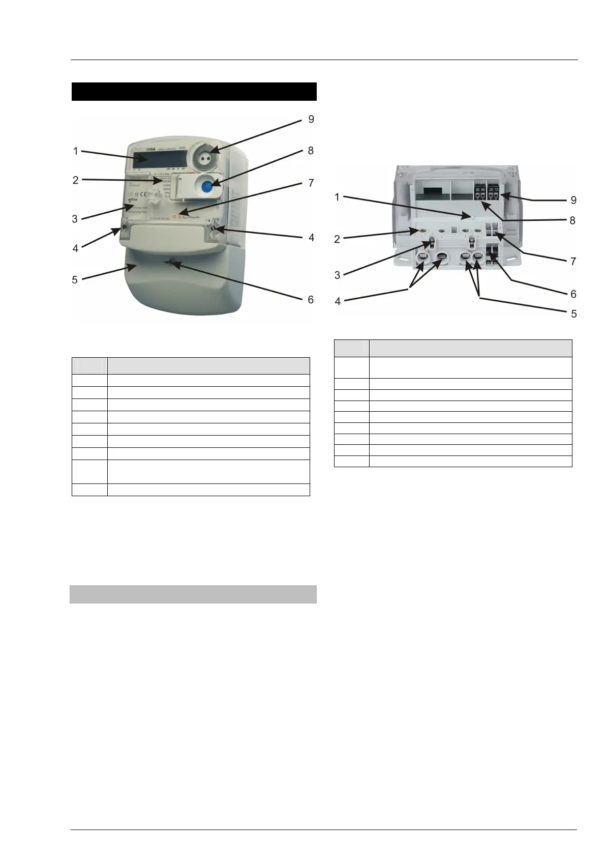
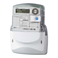
2. Meter appearance (ME37y)
Fig. 3: Meter ME37y constituent parts
ITEM DESCRIPTION
1 Liquid crystal display (LCD)
2 Meter tehnical data
3 Legend for data displayed on LCD
4 A meter cover sealing screw
5 A terminal cover
6 A terminal cover sealing screw
7 Impulse LED
8 Scroll (blue) and Reset (orange) push-
buttons
9 IR optical interface
Two screws for fixing the meter cover (item 4) are
sealed with metrological seals.
The screw for fixing the terminal cover (item 6) and
the Reset push-button lid (item 8) are sealed with
seals of electric utility.
2.1. Meter case (ME37y)
A compact meter case consists of a meter base with
a terminal block and fixing elements for mounting the
meter, a meter cover and a terminal cover. The case
is made of self-distinguishing UV stabilized
polycarbonate which can be recycled. The case
ensures double insulation and IP54 (IEC 60529)
protection level against dust and water penetration.
The top hanger is provided on the back side of the
meter base, under the top edge. On request, an
extended top hanger can be mounted on the meter
base, which ensures the upper fixing hole height of
155 mm above the line connecting the bottom fixing
holes (DIN 43857).
The meter cover is made of transparent polycar-
bon
ate. A nickel-plated iron ring in the right top corner
is utilized for attaching an optical probe to the optical
port. There is a lid which is fixed to the meter cover
with a hinge. The lid covers the Reset push-button
and can be sealed in the closed position.
The terminal block contains current terminals,
auxiliary terminals and potential links for supplying
potential circuits of the meter.
Fig. 4: A terminal block of ME37y meter
ITEM DESCRIPTION
1 A switch for detection of terminal cover
opening
2 A screw for fitting current cables
3 Additional voltage terminals
4 Current terminals
5 Neutral terminals
6 Load control output
7 M-Bus communication interface
8 Second alarm input
9 First alarm input
Current terminals (item 4) are made of galvanized
iron sheet. They are universal terminals for all shapes
and cross sections of connected conductors up to
35 mm
2
. The terminals ensure the same contact
quality with conductors irrespective of whether they
are made of copper or aluminum. Only one screw in a
current terminal reduces time needed for the meter
installation in the field. Due to the indirect pressure on
the conductor it is not damaged.
Up to 8 auxiliary terminals can be fitted in the meter.
They can be utilized for M-Bus, bistable 6 A relay for
load control or alarm inputs. Inputs and outputs are
fitted into the meter regarding the customers request
at meter ordering.
Voltage terminals (item 3) are built into the meter
upon request. They are intended for supplying an
add-on unit from the meter terminal block.
Detectors of opening the terminal cover (item 1) and
the meter cover are built into the meter.
The
terminal cover can be long or short. The meter
connection diagram is stuck on the internal side of
the terminal cover.