Mx37y_Technical_Description_ENG_v2.00.doc
23
─ Single- and three-phase electronic meters with built-in DLC
modem, GSM/GPRS modem or RS485 comm. interface
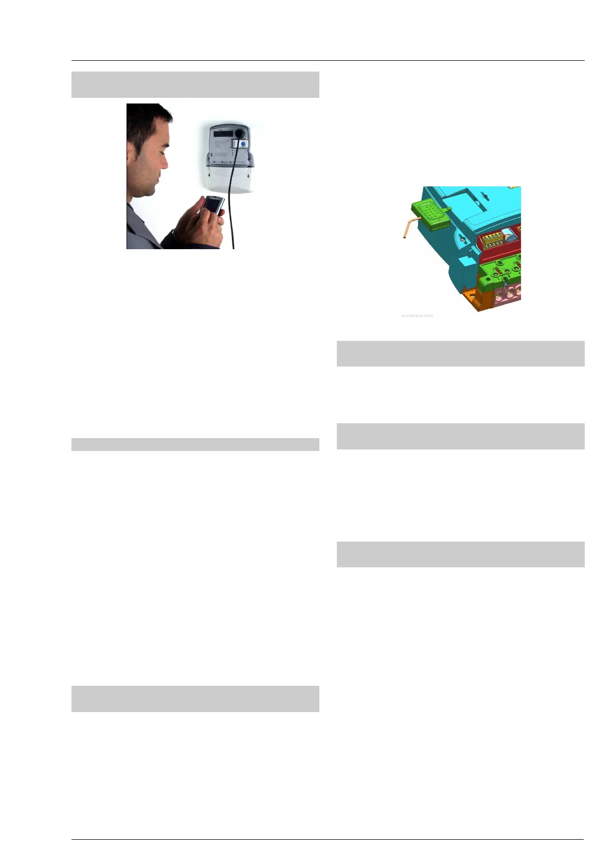
4.7.1. Optical port – IR communication
interface
Fig. 28: Meter readout via an IR optical interface
The optical port complies with the IEC 62056-21 and
is used for local meter programming and data down-
loading. It is located in the right top corner of the
meter. The communication protocol complies with
IEC 62056-21, mode C or DLMS-HDLC IEC 62056-
46. The communication is serial asynchronous with
data transmission rate from 300 bit/sec to 19,200
bit/sec. If data transmission rate of the used optical
probe is lower than 19,200 bit/sec, the maximum
permissible data transmission rate is equal to that
value. If higher data transmission rate is set,
communication via optical port will not be possible.
4.7.2. DLC modem (Mx371)
A DLC modem for remote two-way communication is
built into the meter. The DLC modem is connected to
the low voltage network internally via L3 phase. For
successful communication with the meter it is there-
fore necessary that L3 phase and neutral conductors
are connected to the meter. If the MT371 meter is
installed in a single-phase network, the phase
conductor should be connected to its L3 phase
terminal.
The DLC modem enables two-way communication
wit
h a data concentrator built at the low voltage side
of a substation via low voltage network. Data trans-
mission rate via low voltage network can be up to
1,200 bit/sec. Data transmission rate between the
microcontroller and the DLC modem is serial
asynchronous with data transmission rate of 4,800
bit/sec.
4.7.3. Integrated GSM/GPRS communication
interface with antenna (option) (Mx372)
It enables data transmission via a communication
interface towards the centre for management and
billing or a data concentrator. Data transmission rate
via network is 9600 baud/s, while actual data
transmission rate depends on momentary conditions
in network.
A GSM antenna is built in the meter. It enables
operation in three frequency ranges:
• 900 MHz
• 915 MHz
• 1800 MHz
If a built-in antenna does not meet the needs of
covering the signal, an external antenna can be
mounted. Coupling circuit is placed on the meter
cover and enables a simple mounting of a coupling
module.
Fig. 29: Coupling circuit
4.7.4. RS485 communication interface
(option) (Mx372)
A built-in communication interface enables setting of
meter parameters and a local readout of measuring
results. The protocol for data transfer is IEC 62056 – 46.
4.7.5. M-Bus communication interface
(option)
There is M-Bus communication interface integrated in
Mx37y meters according to EN 13757-2 and EN
13757-3 micro-master specifications. It enables
connection of 4 slave devices (water, gas or/and heat
meters) and max. length of wiring 50 m. Auto-install
procedure is implemented.
4.7.6. Readout via built-in communication
interfaces
Built-in communication interfaces enable:
• Reading of meter registers
• Reading of load-profile recorder
• Reading of meter parameters
• Changing of meter parameters
Communication state is shown on a display, i.e.:
DLC modem: during communication, a flag above a
DRO mark is blinking
RS485 and IR interface: during communication, a
flag above a DRO mark is blinking
GSM/GPRS interface: at successful communication,
several flags are displayed. The flag above the SQ
mark indicates signal strength, the flag above the
REG mark – if present - indicates that the meter is
ready for telecommunication network, and the flag
above the DRO mark indicates that communication is
going on.