Mx37y_Technical_Description_ENG_v2.00.doc
25
─ Single- and three-phase electronic meters with built-in DLC
modem, GSM/GPRS modem or RS485 comm. interface
4.9. Inputs and outputs (ME37y)
Meters can be equipped with up to ten auxiliary
terminals. The following inputs and outputs are
possible:
• Two Alarm inputs (option)
• Output for load control by a bistabile 6 A relay
• M-Bus communication interface
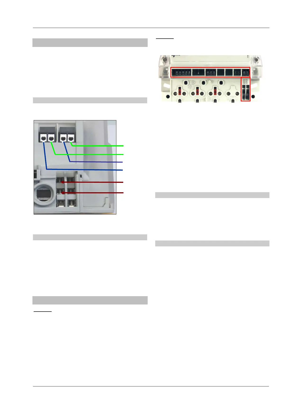
4.9.1. Alarm inputs
Up to two inputs for detecting auxillary alarm are
av
ailable. They are open collector type.
Fig. 32: Position of alarm inputs and outputs on
ME37y meters – bottom view
4.9.2. Load control output
The load control output is a bistabile relay. The relay
is capable of switching 250 V, 6 A. Depending on a
customer request the relay can be controlled by time-
schedule set in the meter (for ON/OFF switching of
appliances by a time-schedule), by calculating trend
of maximum demand (load limiter function), or by
remote command (together with an integrated
switching device – function of remote disconnecting
/reconnecting on customer premises).
4.10. Inputs and outputs (MT37y)
MT371: Auxiliary terminals for meter inputs and
outputs are on the right side of the meter terminal
block compartment. Meters can be provided with up
to six auxiliary terminals. The following inputs and
outputs are possible:
• Impulse output – Optomos relay (option)
• Output for load control with a bistable 6 A relay
(alternatively, instead of the impulse output)
• M-Bus communication interface (option)
• Switching device control output (option)
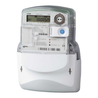
MT372:
Input-output connection terminals are placed
on the right side of the meter terminal block as well
as on the upper additional plate.
Fig. 33: Position of inputs and outputs on MT372 meter –
front view
Eleven auxiliary connection terminals are used for
• Output for load control performed by a relay
• Output for load control performed by an
optomos
• Output for switching device control. On request,
outputs can be used as impulse outputs
• Two alarm inputs (low voltage)
• A bed for a SIM card
• M-Bus communication interface (option)
4.10.1. Inputs
The meter is equipped with two alarm inputs that
occupy four connection terminals.
Input for the alarm is a passive type and is controlled
with voltage on terminals. Control voltage is from 3 V
to 24 V AC/DC (230 V control voltage is available on
request).
4.10.2. Outputs
The meter is equipped with three outputs occupying
six connection terminals.
There are two outputs for load control. One with a
relay that is capable of switching 250 V, 6 A, and
another one that is performed with an Optomos
element and is capable of switching 250 V, 100 mA. It
is possible to control each control output separately,
depending on the written tariff program or on received
command.
On request, meters can be equipped with an external
plug-in unit – a switching device. The switching
device is equipped with a terminal cover, and can be
sealed.
Assembly is simple since one part is inserted into the
meter terminal block, and another part is extension of
the terminal block. The meter with the switching
device as a whole complies with the DIN 43857
standard or the stated fixing dimensions.
Alarm input 1 (+)
Alarm input 2 (-)
Common
Alarm input 2 (+)
Alarm input 1 (-)
Load control output