Mx37y_Technical_Description_ENG_v2.00.doc
30
─ Single- and three-phase electronic meters with built-in DLC
modem, GSM/GPRS modem or RS485 comm. interface
2. The meter should be connected according to the
meter connection diagram that is attached to the
meter terminal cover. Torque of the screws
tightening in the current terminals is 2.5 Nm.
3. The meter operation should be checked:
The LED is turned on (load current is lower
than the meter starting current)
The LED is blinking with frequency proportional
to the engaged electric power (the meter
measures and records energy)
The LED is turned off (the meter is not
energized). In this case it should be checked if:
a. current conductors are connected to the
meter (if not, they should be connected)
b. the potential links are in their bottom position
(if not, the potential link slides should be
pushed to their bottom position)
c. If both upper conditions are fulfilled, it means
that there is no voltage in the mains.
4. Check the L1 L2 L3 indicator (MT37y) on the LCD
if the meter conductors are connected regularly:
The indicators L1, L2 and L3 are displayed –
all three phase voltages are present
Some of the indicators L1, L2 and L3 are not
displayed – voltage in the phase(s) is (are) not
present. In this case, it should be checked if the
current conductors of this (these) phase(s) is
(are) connected to the meter. If they are
connected, a cause of the missing phase
voltage should be found and removed.
The indicators L1, L2 and L3 are blinking –
Reversed phase sequence. The indicator is
blinking only if the rotating magnetic field
rotates counter-clockwise. In this case, the
phase sequence of the connected current wires
should be checked or a place of reversed
phase sequence should be found and its cause
should be removed.
NOTE: The reversed phase sequence does not
influence in the accuracy of energy
measurement!
• Check date and time set in the internal RTC
and, if needed, set the correct values
• If the meter is equipped with GSM/GPRS
communication interface see item 7.1.
• Make billing reset of the meter
• Seal the meter (terminal cover and the lid of the
orange push-button).
7.1. Connection procedure of GSM/GPRS
communication interface
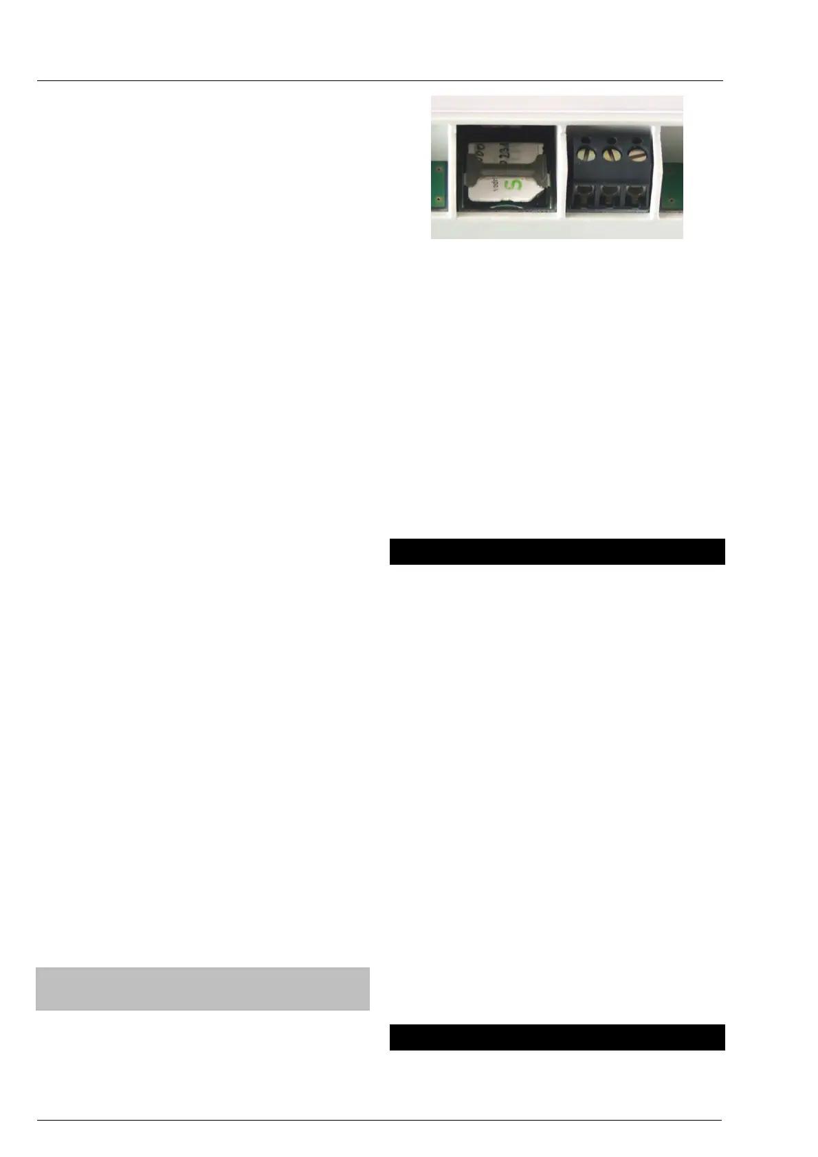
Checking of the presence of a SIM card
1. Remove a terminal cover.
2. Check if a SIM card is inserted as shown in a
figure below
Fig. 36: SIM card bed
3. If a SIM card is not inserted, insert it into the
shown place
Check the GSM/GPRS signal strength on LCD:
a. The flag is permanently lit; good covering
with a GSM/GPRS signal.
b. The flag is blinking; bad covering with the
GSM/GPRS signal. It is recommended to find a
better location for meter installation.
c. The flag is not lit; it is recommended to find a
better location for installation. If the flag is not lit
even at a new place, an external antenna is
required.
Note: limits are adjustable
8. Accessory for meters managing
For meters managing the following accessories are
available:
• For maintaining meter programming and
data down-loading:
MeterView (Iskraemeco software)
Optical probe
Personal computer: PC, desktop, laptop.
The accessory is intended for the person who
maintains and programs meters in a repair shop and
in the field.
• For meter reading and programming in the
field:
MeterRead (Iskraemeco software) for all
types of hand-held computers (Palmtop PC),
utilizing the Windows CE operation system
Optical probe
• For remote meter reading and programming:
SEP2W (Iskraemeco software, with modules
for remote meter reading, data base
management and a module for data
presentation and printing)
Central station – a server with corresponding
software and hardware
9. Meter maintaining
No maintenance is required during the meters life.
The implemented metering technique, built-in