Do you have a question about the Snap-On Diagnostics DGA 1000 and is the answer not in the manual?
Messages to prevent injury/damage, categorized by hazard level.
Instructions on reading safety messages, signal words, and message styles.
Critical safety guidelines for operating the analyzer and vehicle.
Safety precautions related to fire hazards, including extinguisher use.
Safety warnings about vehicle movement and unattended engines.
Safety warnings related to battery hazards and proper connection.
Safety precautions regarding engine compartment hazards and electrical connections.
Warning about relying on erratic test results and potential repair consequences.
Description of controls and features on the analyzer's front panel.
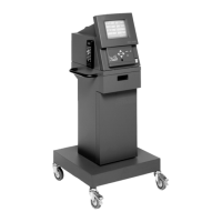
Description of features and components on the analyzer's back panel.
Explanation of universal symbols for navigation on analyzer screens.
Status symbols indicating faults or errors on the Measurement Screen.
Symbols on the Measurement Screen for selecting functions like warnings and standby.
Technical specifications including power, dimensions, measurements, and operating conditions.
Best practices for setting up and using the analyzer for accurate testing.
Instructions for connecting the analyzer to a power source.
Procedures for connecting the analyzer to a vehicle for testing.
Steps for powering on the analyzer and initiating the start-up sequence.
The default screen displaying gas measurements after analyzer power-up.
Explanation of the CO correction formula and its application.
Calculation of Lambda and Air Fuel Ratio using the Brettschneider formula.
Relationship between Lambda, exhaust gases, and catalytic converter efficiency.
Details of menu selection items and their submenus for various tests and functions.
Thorough inspection of the vehicle before performing analysis or troubleshooting.
Entering vehicle information into the analyzer before performing tests.
Procedures for performing general emissions measurements after vehicle setup.
Procedure for performing a two-speed idle test to verify emission concentrations.
Test to diagnose emissions failures due to damaged catalytic converters.
Manual procedure for testing catalytic converter efficiency, including warnings.
Inspection steps before performing the catalytic converter test.
Step-by-step setup for the catalytic converter test, including warm-up and system disabling.
Schedule for periodic maintenance tasks like leak checks.
Test to check for air leaks in the analyzer's sample system.
Test to check for air leaks using vehicle exhaust.
Checking the accuracy of the analyzer's measurement system with calibration gas.
Procedure for calibrating the analyzer using calibration gas.
Status symbols indicating analyzer actions or test failures.
Information on control and error status codes and their solutions.
Overview of systems affecting exhaust diagnosis in gasoline engines.
Performing tests under load using a chassis dynamometer or road testing.
Detailed procedures for on-road and dynamometer testing under load.
Guidelines for analyzing emission data to isolate specific engine problems.
Chart listing possible combinations of exhaust gas values and likely causes.
| Brand | Snap-On Diagnostics |
|---|---|
| Model | DGA 1000 |
| Category | Measuring Instruments |
| Language | English |