EasyManua.ls Logo

Snapper LE317 - Section II - MACHINE OPERATION; Fuel Reouirements; Fuel Precautions; Operational Controls.5-6

Snapper LE317
24 pages
To Next Page IconTo Next Page
To Previous Page IconTo Previous Page
Loading...
Section
II
-
MACHINE
OPERATION
2.1
The
SNAPPER
LE317
or
LE319
is
powered
by
a
3
Horsepower,
2
cycle
engine
and
will
clear
a
path
either
17
inches
or
19
inches
wide
and
will
throw
snow
from
3
to
20
feet
away
depending
on
the
Discharge
Deflector
setting
and
snow
conditions.
Due
to
the
light
weight
of
these
units,
they
are
ideally
suited
for
clearing
decks
and
porches.
These
units
have
a
fuel
capacity
of
1.25
quarts
which
will
result
in
an
operational
time
of
1
1/4
to
1
3/4
hours.
2.2
Save
this
manual
and
the
Engine
Manual
and
review
at
the
start
of
each
new
season.
Pay
particular
attention
to
the
important
Safety
Instructions
and
to
the
Warning
Decals
on
the
unit.
A.
Fuel
is
highly
volatile.
Keep
safely
away
from
ignition
producing
appliances
and
in
well-
ventilated
area
where
fumes
can
be
dissipated.
Fill
fuel
tank
with
correct
gasoline/oil
mixture
as
specified
in
the
Engine
Owner’s
Manual.
B.
Wipe
up
any
spilled
fuel.
C.
Do
not
use
fuels
which
have
been
sitting
for
a
long
period
of
time
(one
month
maximum).
2.5
OPERATIONAL
CONTROLS
-
IDENTIFICATION
&
LOCATION
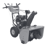
(Refer
to
Figure
1.1)
2.3
FUEL
REQUIREMENTS
-
2
CYCLE
ENGINE
WARNING
USE
A
50;T
RATIO
GASOLINE/OIL
MIXTURE
ONLY
IN
THE
SNAPPER
LE317
OR
LE319
SNOW
THROWER.
A.
For
proper
lubrication,
the
engine
must
operate
on
an
exact
mixture
of
gasoline
and
2
cycle
air-cooled
engine
oil.
Use
a
50
to
1
mixture.
Use
a
good
quality
regular
grade
leaded
or
unleaded
gasoline
and
SNAPPER
special
formulated
2-cycle
engine
oil.
The
50
to
1
ratio
equals
2.56
ounces
of
oil
to
each
gallon
(U.S.
Standard)
of
gasoline,
(or
10.24
oz.
to
4
gallons
gasoline).
Refer
to
the
following
chart
for
correct
50
to
1
ratio
mixtures:
50:1
RATIO
-
U.S.
STANDARD
FLUID
MEASUREMENTS
GALLONS
GASOLINE
1
2
3
4
5
OUNCES
2-CYCLE
OIL
2.56
5.12
7.68
10.24
12.80
PRIMER
-
Located
at
center
of
Control
Panel.
Used
to
inject
fuel
into
the
carburetor
during
initial
startups.
CHOKE
-
Red
Knob
located
in
slot
in
the
bottom
cover
on
the
L.H.
side
of
the
machine.
Moves
to
the
right
to
choke.
Used
during
initial
engine
startups.
IGNITION
SWITCH
&
KEY
-
Located
at
center
of
Control
Panel.
Used
to
turn
engine
on
or
off.
PULL
ROPE
&
KNOB
-
Located
at
center
of
Control
Panel
below
Primer
&
Keyswitch.
Used
to
start
engine.
ELECTRIC
START
BUTTON
(If
Equipped)
-
Black
Button
on
the
Control
Panel
on
the
R.H.
side.
Depress
to
activate
Electric
Starter,
and
release
to
deactivate
Electric
Starter.
ELECTRIC
START
110
Volt
(Household
Current)
Receptacle
-
Male
Terminals
located
in
recess
in
bottom
cover
on
the
R.H.
side.
B.
Pre-Mix
the
fuel
in
an
approved
container
while
observing
all
safety
precautions
relating
to
handling
of
fuel.
Add
some
gasoline
first,
then
the
oil.
Close
the
container
and
shake
vigorously
to
thoroughly
mix
the
fuel;
open
the
container
and
add
the
remaining
amount
of
gasoline
to
correct
the
ratio.
Shake
the
container
to
mix
the
fuel
each
time
before
filling
the
fuel
tank.
DO
NOT
add
fuel
to
unit
while
hot...allow
engine
to
cool
for
10
minutes.
2.4
FUEL
PRECAUTIONS
A
DANGER^
GASOLINE
IS
HIGHLY
FLAMMABLE!
DO
NOT
SMOKE
WHILE
HANDLING
OR
NEAR
GASOLINE!
DO
NOT
USE
OR
STORE
GASOLINE
NEAR
OPEN
FLAME
OR
SPARK-
PRODUCING
DEVICES!
AUGER
CLUTCH
CONTROL
-
Wire
form
located
on
the
top
side
of
the
Upper
Handle.
Rotates
back
and
downward
causing
the
Auger
to
rotate.
Releasing
the
control
will
allow
it
to
return
to
its
original
position
and
stop
rotation
of
the
Auger.
UPPER
HANDLE
-
Extending
rearward
from
Top
Cover.
Used
to
control
motion
of
the
unit.
By
lifting
upward
slightly
(approximately
1
1/2")
on
handle
and
rotating
the
Auger
Clutch
Control
rearward,
the
Auger
will
contact
the
ground
and
propel
the
unit
fonward.
5

Related product manuals